


4-14 System Board
PCI/IDE Ports
The system board supports two high-performance PCI/IDE ports: a primary port
and a secondary port on the system board. Each port supports up to two devices
for a total of four IDE devices. The primary PCI/IDE port has an enhanced IDE
interface that supports PIO Mode 4 devices with 16 MB per second 32-bit wide
data transfers on the high-performance PCI local bus. Each port supports Ultra
DMA/33.
The installed hard drive is connected to the primary PCI/IDE connector with a
three-connector cable. If a CD-ROM drive is included in the system, it is
connected to the secondary PCI/IDE port with a three-connector cable. A second
device can be added to the primary PCI/IDE port.
Parallel Interface
The system has a 25-pin bidirectional parallel port on the system board. Port
specifications conform to the IBM-PC standards. The port supports Enhanced
Capabilities Port (ECP) and Enhanced Parallel Port (EPP) modes for devices
that require ECP or EPP protocols. The protocols allow high-speed bi-
directional transfer over a parallel port and increase parallel port functionality
by supporting more devices.
The BIOS has automatic ISA printer port sensing that works with most devices.
If the BIOS detects an ISA printer port mapped to the same address, the built-in
printer port is disabled. (Verify in the BIOS Setup that printer ports mapped to
the same address are enabled or disabled appropriately.) The BIOS also sets the
first parallel interface port it finds as LPT1 and the second port it finds as LPT2.
The interrupt is set at IRQ7 via the BIOS Setup utility. Software-selectable base
addresses are 228h, 378h, and 278h.
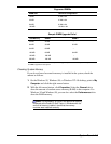
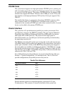
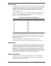
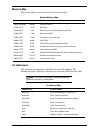
Sets of I/O addresses for the parallel port are given in the following table (see
Section 2, “System Configuration,” for interrupt levels). This is a list of all
possible configurations; the parallel port uses only one set.
Parallel Port Addresses
Starting I/O Address Port
378 LPT1
278 LPT2
228 LPT3
378 LPT1
278 LPT2
228 LPT3
Parallel interface signals are output through the system board’s 25-pin,
D-subconnector. The connector is located at the back of the system unit.