


117
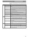
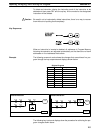
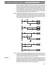
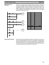
When drawing a ladder diagram, be careful not to use TR bits unless necessary.
Often the number of instructions required for a program can be reduced and
ease of understanding a program increased by redrawing a diagram that would
otherwise required TR bits. In both of the following pairs of diagrams, the bottom
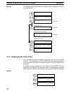
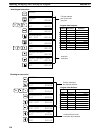
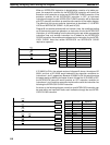
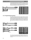
versions require fewer instructions and do not require TR bits. In the first exam-
ple, this is achieved by reorganizing the parts of the instruction block: the bottom
one, by separating the second OUTPUT instruction and using another LOAD
instruction to create the proper execution condition for it.
Note Although simplifying programs is always a concern, the order of execution of
instructions is sometimes important. For example, a MOVE instruction may be
required before the execution of a BINARY ADD instruction to place the proper
data in the required operand word. Be sure that you have considered execution
order before reorganizing a program to simplify it.
Instruction 1
00000
Instruction 2
00001
TR 0
Instruction 2
00000
Instruction 1
00001
Instruction 1
00000
Instruction 2
00003
TR 0
00001
00004
00002
00001 00003
00000
00004
00002
00001
Instruction 1
Instruction 2
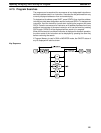
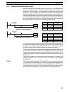
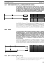
Note TR bits are only used when programming using mnemonic code. They are not
necessary when inputting ladder diagrams directly. The above limitations on the
number of branching points requiring TR bits, and considerations on methods to
reduce the number of programming instructions, still hold.
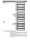
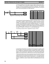
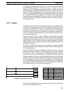
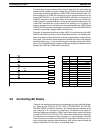
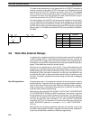
Interlocks The problem of storing execution conditions at branching points can also be
handled by using the INTERLOCK (IL(02)) and INTERLOCK CLEAR (ILC(03))
instructions to eliminate the branching point completely while allowing a specific
execution condition to control a group of instructions. The INTERLOCK and
INTERLOCK CLEAR instructions are always used together.
Inputting, Modifying, and Checking the Program Section 4-7