


40
3-4-3 Link System Flags and Control Bits
Use of the following SR bits depends on the configuration of any Link Systems to
which your PC belongs. These flags and control bits are used when Link Units,
such as PC Link Units, Remote I/O Units, or Host Link Units, are mounted to the
PC Racks or to the CPU Unit. For additional information, consult the System
Manual for the particular Units involved.
The following bits can be employed as work bits when the PC does not belong to
the Link System associated with them.
Host Link Systems
Both Error flags and Restart bits are provided for Host Link Systems. Error flags
turn ON to indicate errors in Host Link Units. Restart bits are turned ON and then
OFF to restart a Host Link Unit. SR bits used with Host Link Systems are summa-
rized in the following table. Rack-mounting Host Link Unit Restart bits are
not effective for the Multilevel Rack-mounting Host Link Units. Refer to the
Host Link System Manual for details.
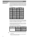
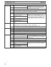
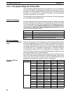
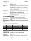
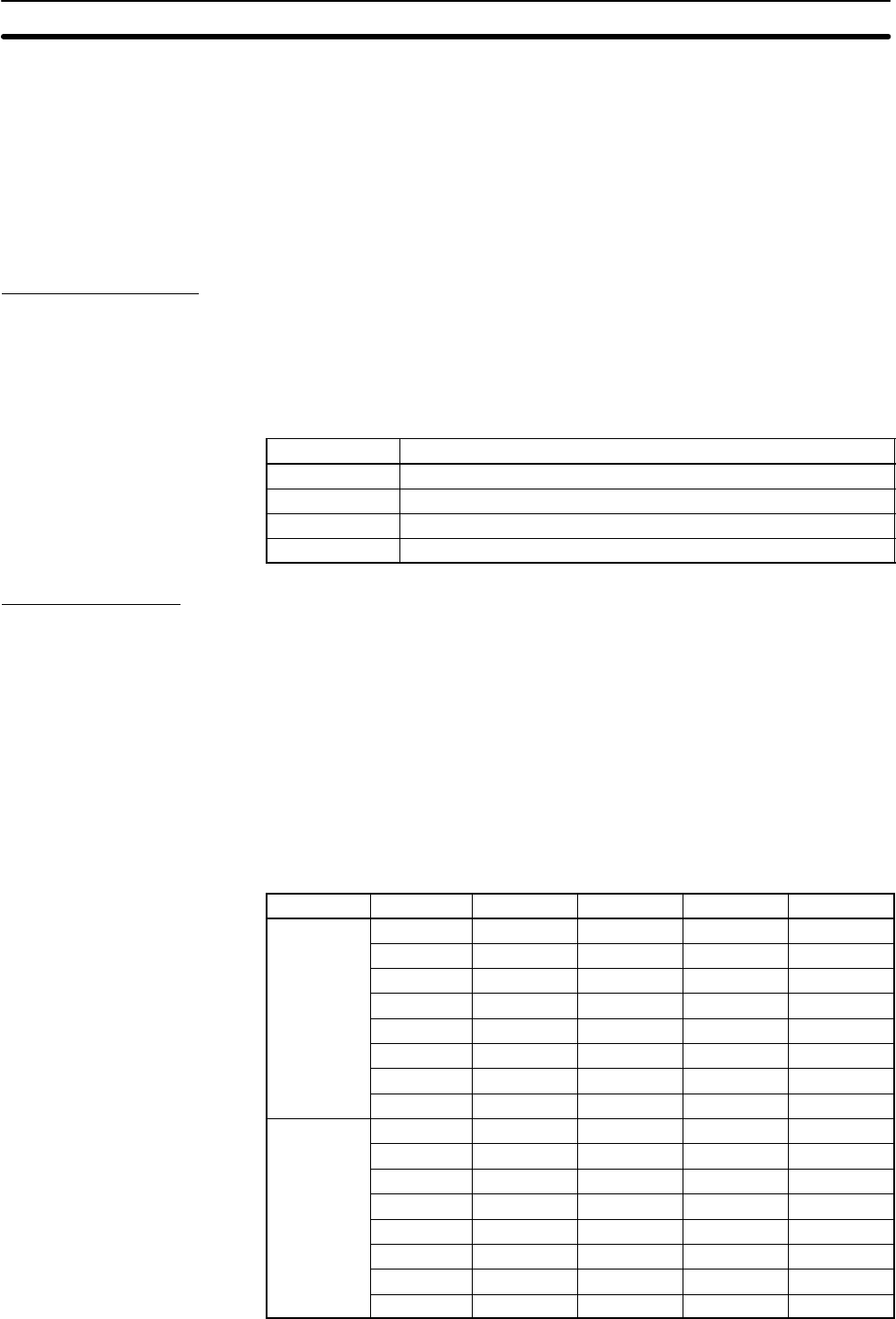
Bit Flag
25206 Rack-mounting Host Link Unit Level 1 Error Flag
25207 Rack-mounting Host Link Unit Level 1 Restart Bit
25213 Rack-mounting Host Link Unit Level 0 Restart Bit
25311 Rack-mounting Host Link Unit Level 0 Error Flag
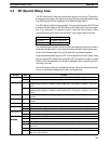
PC Link Systems
When the PC belongs to a PC Link System, words 247 through 250 are used to
monitor the operating status of all PC Link Units connected to the PC Link Sys-
tem. This includes a maximum of 32 PC Link Units. If the PC is in a Multilevel PC
Link System, half of the PC Link Units will be in a PC Link Subsystem in operating
level 0; the other half, in a Subsystem in operating level 1. The actual bit assign-
ments depend on whether the PC is in a Single-level PC Link System or a Multi-
level PC Link System. Refer to the PC Link System Manual for details. Error and
Run Flag bit assignments are described below.
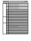
Bits 00 through 07 of each word are the Run flags, which are ON when the PC
Link Unit is in RUN mode. Bits 08 through 15 are the Error flags, which are ON
when an error has occurred in the PC Link Unit. The following table shows bit
assignments for Single-level and Multi-level PC Link Systems.
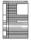
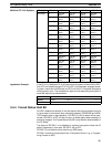
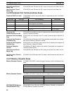
Flag type Bit no. SR 247 SR 248 SR 249 SR 250
Run flags 00 Unit #24 Unit #16 Unit #8 Unit #0
01 Unit #25 Unit #17 Unit #9 Unit #1
02 Unit #26 Unit #18 Unit #10 Unit #2
03 Unit #27 Unit #19 Unit #11 Unit #3
04 Unit #28 Unit #20 Unit #12 Unit #4
05 Unit #29 Unit #21 Unit #13 Unit #5
06 Unit #30 Unit #22 Unit #14 Unit #6
07 Unit #31 Unit #23 Unit #15 Unit #7
Error flags 08 Unit #24 Unit #16 Unit #8 Unit #0
09 Unit #25 Unit #17 Unit #9 Unit #1
10 Unit #26 Unit #18 Unit #10 Unit #2
11 Unit #27 Unit #19 Unit #11 Unit #3
12 Unit #28 Unit #20 Unit #12 Unit #4
13 Unit #29 Unit #21 Unit #13 Unit #5
14 Unit #30 Unit #22 Unit #14 Unit #6
15 Unit #31 Unit #23 Unit #15 Unit #7
PC Link Unit Error and Run
Flags
Single-level PC Link
Systems
SR (Special Relay) Area Section 3-4