


149
5-8 Ladder Diagram Instructions
Ladder Diagram instructions include Ladder instructions and Logic Block
instructions and correspond to the conditions on the ladder diagram. Logic block
instructions are used to relate more complex parts.
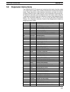
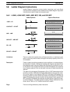
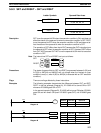
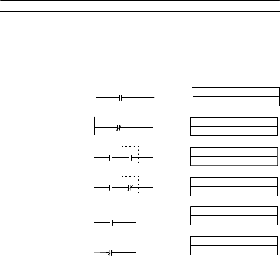
5-8-1 LOAD, LOAD NOT, AND, AND NOT, OR, and OR NOT
B: Bit
IR, SR, AR, HR, TC, LR, TR
Ladder Symbols Operand Data Areas
LOAD – LD
B
B: Bit
IR, SR, AR, HR, TC, LR
LOAD NOT – LD NOT
B
B: Bit
IR, SR, AR, HR, TC, LR
AND – AND
B
B: Bit
IR, SR, AR, HR, TC, LR
AND NOT – AND NOT
B
B: Bit
IR, SR, AR, HR, TC, LR
OR – OR
B
B: Bit
IR, SR, AR, HR, TC, LR
OR NOT – OR NOT
B
Limitations There is no limit to the number of any of these instructions, or restrictions in the
order in which they must be used, as long as the memory capacity of the PC is
not exceeded.
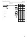
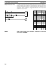
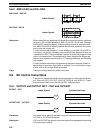
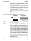
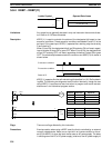
Description These six basic instructions correspond to the conditions on a ladder diagram.
As described in Section 4 Writing and Inputting the Program, the status of the
bits assigned to each instruction determines the execution conditions for all oth-
er instructions. Each of these instructions and each bit address can be used as
many times as required. Each can be used in as many of these instructions as
required.
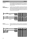
The status of the bit operand (B) assigned to LD or LD NOT determines the first
execution condition. AND takes the logical AND between the execution condi-
tion and the status of its bit operand; AND NOT, the logical AND between the
execution condition and the inverse of the status of its bit operand. OR takes the
logical OR between the execution condition and the status of its bit operand; OR
NOT, the logical OR between the execution condition and the inverse of the sta-
tus of its bit operand. The ladder symbol for loading TR bits is different from that
shown above. Refer to 4-4-3 Ladder Instructions for details.
Flags There are no flags affected by these instructions.
Ladder Diagram Instructions Section 5-8