


12
2-1 CPU Unit Components
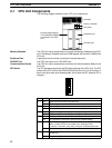
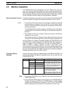
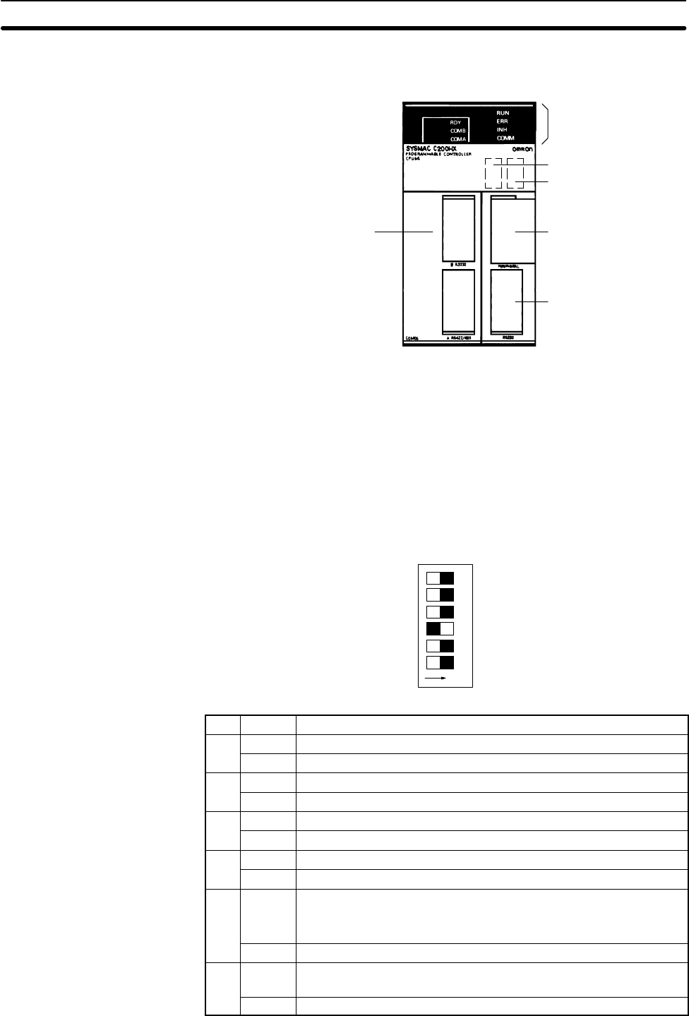
The following diagram shows the main CPU Unit components.
Communications Board
(The C200HW-COM06-E
is mounted to this CPU
Unit.)
Indicators
Memory Cassette
DIP switch
Peripheral port
RS-232C port
Memory Cassette The CPU Unit has a compartment to connect the Memory Cassette to the CPU
Unit. The Memory Cassette works as a RAM together with the built-in RAM of the
CPU Unit.
Peripheral Port A peripheral device can be connected to the peripheral port.
RS-232C Port The CPU Unit has a built-in RS-232C port.
Communications Board The CPU Unit has a compartment to connect the Communications Board to the
CPU Unit.
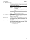
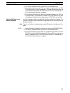
DIP Switch The PC operates according to the DIP switch settings of the CPU Unit. The DIP
switch of the CPU Unit for the C200HX/HG/HE has six pins. For the function of
each of the pins, refer to the following table. (All six pins are OFF when the PC is
shipped.)
123456
ON
OFF⇔ON
Pin Setting Function
1 ON Data cannot be written to the UM area.
OFF Data can be written to the UM area.
2 ON Memory Cassette data is read automatically at startup.
OFF Memory Cassette data is not read automatically at startup.
3 ON Programming Console displays messages in English.
OFF Programming Console displays messages in Japanese.
4 ON The expansion instructions can be set.
OFF The expansion instructions cannot be set (default setting).
5 ON Sets the following conditions for the communications port (including
when a CQM1-CIF02 is connected to the Peripheral Port):
1 start bit, 7 data bits, even parity, 2 stop bit, 9,600 bps baud rate
OFF Cancels the above settings.
6 ON Programming Console is in expansion terminal mode (AR 0712 is
turned ON).
OFF Programming Console is in normal mode (AR 0712 is turned OFF).
CPU Unit Components Section 2-1