


342
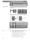
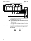
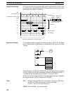
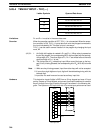
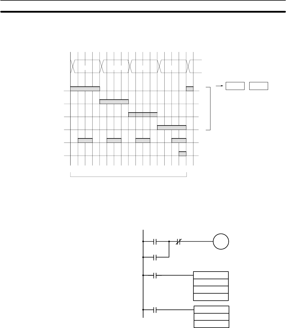
Using the Instruction If the input word for connecting the digital switch is specified at for word A, and
the output word is specified for word B, then operation will proceed as shown
below when the program is executed.
00
01
02
03
04
05
Wd 0
10
0
10
1
10
2
10
3
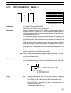
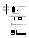
D+1 D
Four digits: 00 to 03
Eight digits: 00 to 03, 04 to 07
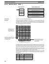
0 1 2 3 4 5 6 7 8 9 10 11 12 13 14 15 16
IW
When only 4 digits are read,
only word D is used.
Leftmost
4 digits
Rightmost
4 digits
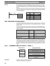
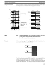
16 cycles to complete one round of execution
Input data
CS signal
1 Round Flag
RD (read) signal
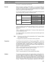
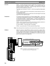
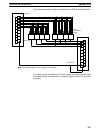
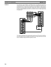
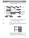
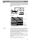
Application Example This example shows a program for reading 8 digits in BCD from the digital
switch. Assume that the digital switch is connected to IR 000 (input) and IR 100
(output).
@MOV(21)
HR51
DM0000
DSW
000
100
HR51
05000
00015 10005
05000
05000
10005
When IR 00015 turns ON, the IR 05000 will hold itself ON until the One Round
Flag (IR 10005) turns ON upon completion of one round of reading by DSW(––).
The data set from the digital switch by DSW(––) is stored in HR 51.
When the One Round Flag (10005) turns ON after reading has been completed,
the number stored in HR 51 is transferred to DM 0000.
Flags ER: Indirectly addressed DM word is non-existent. (Content of DM word is
not BCD, or the DM area boundary has been exceeded.)
R and R+1 are not in the same data area.
25410: ON while DSW(––) is being executed.
Advanced I/O Instructions Section 5-28