65
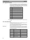
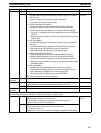
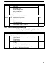
Word(s) DefaultFunctionBit(s)
DM 6654 00 to 07 Start code (RS-232C)
00 to FF (binary)
0000
08 to 15 12 to 15 of DM 6653 set to 0:
Number of bytes received
00: Default setting (256 bytes)
01 to FF: 1 to 255 bytes
12 to 15 of DM 6653 set to 1:
End code (RS-232C)
00 to FF (binary)
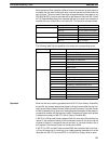
Error Settings (DM 6655)
The following settings are accessed continually while the PC is ON.
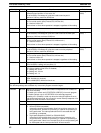
DM 6655 00 to 03 Interrupt programming error enable
0: Detect interrupt programming errors
1: Do not detect
Detect
04 to 07 Reserved ---
08 to 11 Cycle time monitor enable
0: Detect long cycles as non-fatal errors
1: Do not detect long cycles
Detect
12 to 15 Low battery error enable
0: Detect low battery voltage as non-fatal error
1: Do not detect low battery voltage
Detect
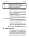
3-6-5 Communications Board Settings
DM 6550 through DM 6554 contain the communications settings for Commu-
nications Board port B and DM 6555 through DM 6559 contain the communica-
tions settings for Communications Board port A.
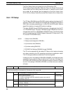
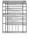
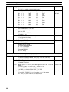
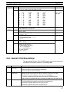
Word(s) Bit(s) Function Default
Communications Board Port B Settings (DM 6550 to DM 6554)
The following settings are accessed continually while the PC is ON.
DM 6550 00 to 03 Port settings
0: Standard (1 start bit, 7-bit data, even parity, 2 stop bits, 9,600 bps)
1: Settings in DM 6551
Standard
04 to 07 CTS control setting
0: Disable CTS control
1: Enable CTS control
Disable
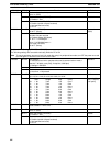
08 to 11 Words linked for 1:1 PC Link (Cannot be changed once set in the 1:1 PC
Link Master.)
0: LR 00 to LR 63; 1: LR 00 to LR 31; 2: LR 00 to LR 15
Maximum PT node number for 1:N NT Link
1 to 7 BCD (1 to 3 with a C200HE-CPUjj-E PC)
LR 00 to LR 63
12 to 15 Communications mode
0: Host Link; 1: RS-232C; 2: 1:1 PC Link slave; 3: 1:1 PC Link master;
4: 1:1 NT Link; 5: 1:N NT Link; 6: Protocol Macro
Host Link
DM (Data Memory) Area Section 3-6


