221
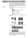
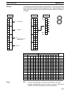
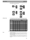
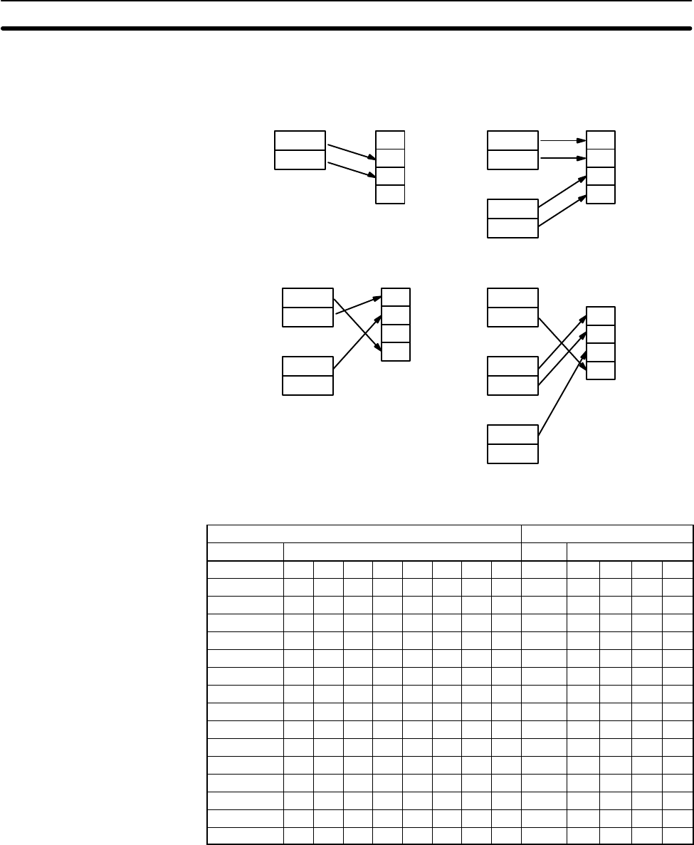
Some examples of Di values and the 8-bit ASCII to 4-bit hexadecimal conver-
sions that they produce are shown below.
0
1
2
3
D
Di: 0011
S
Di: 0030
Di: 0133Di: 0023
1
st
byte
2
nd
byte
S
1
st
byte
2
nd
byte
S+1
1
st
byte
2
nd
byte
0
1
2
3
D
S
1
st
byte
2
nd
byte
S+1
1
st
byte
2
nd
byte
0
1
2
3
D
S
1
st
byte
2
nd
byte
S+1
1
st
byte
2
nd
byte
0
1
2
3
D
S+2
1
st
byte
2
nd
byte
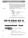
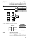
ASCII Code Table The following table shows the ASCII codes before conversion and the hexadeci-
mal values after conversion. Refer to Appendix I for a table of ASCII characters.
Original data Converted data
ASCII Code Bit status (See note.) Digit Bits
30 * 0 1 1 0 0 0 0 0 0 0 0 0
31 * 0 1 1 0 0 0 1 1 0 0 0 1
32 * 0 1 1 0 0 1 0 2 0 0 1 0
33 * 0 1 1 0 0 1 1 3 0 0 1 1
34 * 0 1 1 0 1 0 0 4 0 1 0 0
35 * 0 1 1 0 1 0 1 5 0 1 0 1
36 * 0 1 1 0 1 1 0 6 0 1 1 0
37 * 0 1 1 0 1 1 1 7 0 1 1 1
38 * 0 1 1 1 0 0 0 8 1 0 0 0
39 * 0 1 1 1 0 0 1 9 1 0 0 1
41 * 1 0 1 0 0 0 1 A 1 0 1 0
42 * 1 0 1 0 0 1 0 B 1 0 1 1
43 * 1 0 1 0 0 1 1 C 1 1 0 0
44 * 1 0 1 0 1 0 0 D 1 1 0 1
45 * 1 0 1 0 1 0 1 E 1 1 1 0
46 * 1 0 1 0 1 1 0 F 1 1 1 1
Note The leftmost bit of each ASCII code is adjusted for parity.
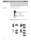
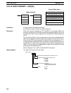
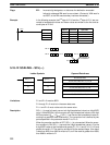
Parity The leftmost bit of each ASCII character (2 digits) is automatically adjusted for
either even or odd parity.
With no parity, the leftmost bit should always be zero. With odd or even parity, the
leftmost bit of each ASCII character should be adjusted so that there is an odd or
even number of ON bits.
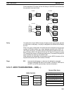
If the parity of the ASCII code in S does not agree with the parity specified in Di,
the ER Flag (SR 25503) will be turned ON and the instruction will not be
executed.
Data Conversion Section 5-18


