


37
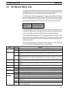
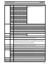
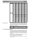
Word(s) FunctionBit(s)
274
00 Special I/O Unit #0 Restart Flag
These flags will turn ON during restart processing.
01 Special I/O Unit #1 Restart Flag
These flags will not turn ON for Units on Slave
02 Special I/O Unit #2 Restart Flag
Racks.
03 Special I/O Unit #3 Restart Flag
04 Special I/O Unit #4 Restart Flag
05 Special I/O Unit #5 Restart Flag
06 Special I/O Unit #6 Restart Flag
07 Special I/O Unit #7 Restart Flag
08 Special I/O Unit #8 Restart Flag
09 Special I/O Unit #9 Restart Flag
10 Special I/O Unit #A Restart Flag
11 Special I/O Unit #B Restart Flag
12 Special I/O Unit #C Restart Flag
13 Special I/O Unit #D Restart Flag
14 Special I/O Unit #E Restart Flag
15 Special I/O Unit #F Restart Flag
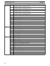
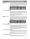
275
00 PC Setup Error (DM 6600 to DM 6605)
01 PC Setup Error (DM 6613 to DM 6623)
02 PC Setup Error (DM 6645 to DM 6655)
03 Reserved by system (not accessible by user)
04 Changing RS-232C Setup Flag
05 Reserved by system (not accessible by user)
06 to 07 Reserved by system (not accessible by user)
08 to 15 Reserved by system (not accessible by user)
276
00 to 07 Minutes (00 to 59)
Indicates the current time in BCD.
08 to 15 Hours (00 to 23)
277 to 279 00 to 15 Used for keyboard mapping. See page 412.
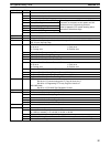
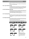
280 00 to 15 Group-2 High-density I/O Unit Error Flags for Units 0 to F
(AR 0205 to AR 0214 also function as Error Flags for Units 0 to 9.)
281 00 to 15 Special I/O Unit Restart Bits for Units 0 to F
(Units 0 to 9 can also be restarted with Special I/O Unit Restart Bits AR 0100 to AR 0109.)
• To restart a Special I/O Unit, either use for force-set/reset operation to turn the Restart Bit ON
and OFF, or turn OFF the power and then turn it ON again.
• Follow the same procedure as above for starting PC Link Units.
282 00 to 15 Special I/O Unit Error Flags for Units 0 to F
(AR 0000 to AR 0009 also function as Error Flags for Units 0 to 9.)
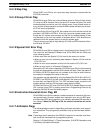
283 to 286 00 to 15 Communications Board monitoring area
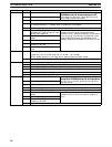
287 to 288 00 to 15 Communications Board interrupt data area
289
00 to 07 Communications Board general monitoring area
08 Communications Board Port A Instruction Execution Flag
09 to 10 Used by Communications Board Port A instructions
11 Communications Board Port A Instruction Abort Bit
12 Communications Board Port B Instruction Execution Flag
13 to 14 Used by Communications Board Port B instructions
15 Communications Board Port B Instruction Abort Bit
290 to 293 00 to 15 Macro Area inputs.
294 to 297 00 to 15 Macro Area outputs.
298 to 299 00 to 15 Reserved by system (not accessible by user)
SR (Special Relay) Area Section 3-4