47
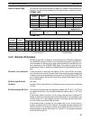
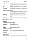
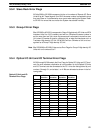
Memory Cassette Flag SR bit 26915 turns ON when a Memory Cassette is mounted.
Save UM to Cassette Flag SR bit 27000 turns ON when UM data is read to a Memory Cassette in Program
Mode. Bit will automatically turn OFF. An error will be produced if turned ON in
any other mode.
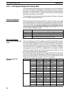
SR bit 27001 turns ON when data is loaded into UM from a Memory Cassette in
Program Mode. Bit will automatically turn OFF. An error will be produced if
turned ON in any other mode.
SR bit 27002 turns ON when data has been compared between DM and a
Memory Cassette. SR bit 27003 is turned OFF if the data in the Memory Cas-
sette matches and it is turned ON if the data does not match.
3-4-22 Data Transfer Error Bits
Data will not be transferred from UM to the Memory Cassette if an error occurs
(except for Board Checksum Error). Detailed information on checksum errors
occurring in the Memory Cassette will not be output to SR 272 because the in-
formation is not needed. Repeat the transmission if SR 27015 is ON.
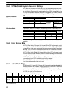
SR bit 27011 turns ON when an attempt is made to transfer the UM used for the
SYSMAC NET data link table while the data link is active.
SR bit 27012 turns ON when the PC is not in Program Mode and data transfer is
attempted.
SR bit 27013 turns ON when the PC is in Read-only Mode and data transfer is
attempted.
SR bit 27014 turns ON when data transfer is attempted and available UM is in-
sufficient.
SR bit 27015 turns ON when data transfer is attempted and a Board Checksum
error occurs.
3-4-23 Ladder Diagram Memory Areas
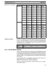
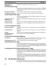
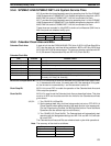
SR 27100 to SR 27107 indicate the amount of ladder program stored in a
Memory Cassette. Ladder-only Files:
04: 4 KW; 08: 8 KW; 12: 12 KW; ... (32: 32 KW)
00:Memory Cassette contents not UM or there is no file.
SR 27108 to SR 27115 indicate the CPU Unit’s ladder program size and type.
Specifications are the same as for bits 00 to 07.
3-4-24 Memory Error Flags
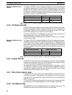
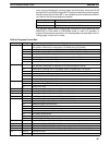
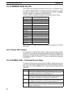
SR bit 27211 turns ON when a PC Setup Checksum error occurs.
SR bit 27212 turns ON when a Ladder Checksum error occurs.
SR bit 27213 turns ON when an instruction change vector area error occurs.
SR bit 27214 turns ON when a Memory Cassette is connected or disconnected
during operations.
Load UM from Cassette
Flag
Collation (Between DM and
Memory Cassette)
Transfer Error Flag:
Active Data Link
Transfer Error Flag:
Not PROGRAM Mode
Transfer Error Flag:
Read Only
Transfer Error Flag:
Insufficient Capacity or No
UM
Transfer Error Flag: Board
Checksum Error
Memory Cassette Ladder
Diagram Size Area
CPU Unit Ladder Diagram
Size and Type
Memory Error Flag: PC
Setup Error
Memory Error Flag: Ladder
Checksum Error
Memory Error Flag:
Instruction Change Error
Memory Error Flag: Memory
Cassette Disconnect Error
SR (Special Relay) Area Section 3-4


