


D-13360-A2-GB20-20 December 1996
Pin Assignments
Overview D-1. . . . . . . . . . . . . . . . . . . . . . . . . . . . . . . . . . . . . . . . . . . . . . . . . . . . . . . . . . . . . . . . . . . . . . . . . .
HDSL Network Interface D-1. . . . . . . . . . . . . . . . . . . . . . . . . . . . . . . . . . . . . . . . . . . . . . . . . . . . . . . . . . . . .
G.703 DTE Interface D-2. . . . . . . . . . . . . . . . . . . . . . . . . . . . . . . . . . . . . . . . . . . . . . . . . . . . . . . . . . . . . . . . .
AUX Port Interface D-3. . . . . . . . . . . . . . . . . . . . . . . . . . . . . . . . . . . . . . . . . . . . . . . . . . . . . . . . . . . . . . . . . .
COM Port Interface D-4. . . . . . . . . . . . . . . . . . . . . . . . . . . . . . . . . . . . . . . . . . . . . . . . . . . . . . . . . . . . . . . . . .
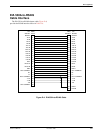
EIA 530A Port Interface Connector D-6. . . . . . . . . . . . . . . . . . . . . . . . . . . . . . . . . . . . . . . . . . . . . . . . . . . . .
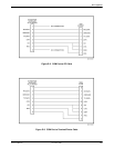
EIA 530A-to-RS449 Cable Interface D-7. . . . . . . . . . . . . . . . . . . . . . . . . . . . . . . . . . . . . . . . . . . . . . . . . . . .
EIA 530A-to-V.35 Cable Interface D-9. . . . . . . . . . . . . . . . . . . . . . . . . . . . . . . . . . . . . . . . . . . . . . . . . . . . . .
EIA 530A-to-X.21 Cable Interface D-11. . . . . . . . . . . . . . . . . . . . . . . . . . . . . . . . . . . . . . . . . . . . . . . . . . . . . .
Power Input Connector D-13. . . . . . . . . . . . . . . . . . . . . . . . . . . . . . . . . . . . . . . . . . . . . . . . . . . . . . . . . . . . . . .
Optional DC Power Cable D-13. . . . . . . . . . . . . . . . . . . . . . . . . . . . . . . . . . . . . . . . . . . . . . . . . . . . . . . . . . . .
External Clock Interface D-14. . . . . . . . . . . . . . . . . . . . . . . . . . . . . . . . . . . . . . . . . . . . . . . . . . . . . . . . . . . . . .
Overview
The E1 NTU is shipped with a power module. Various
other interconnecting cables are available from the
company. For cable feature numbers, refer to Appendix H,
Equipment List. This appendix describes the connector pin
assignments for the E1 NTU, Paradyne cables, and
customer-supplied cables.
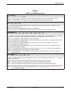
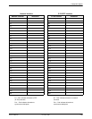
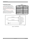
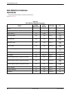
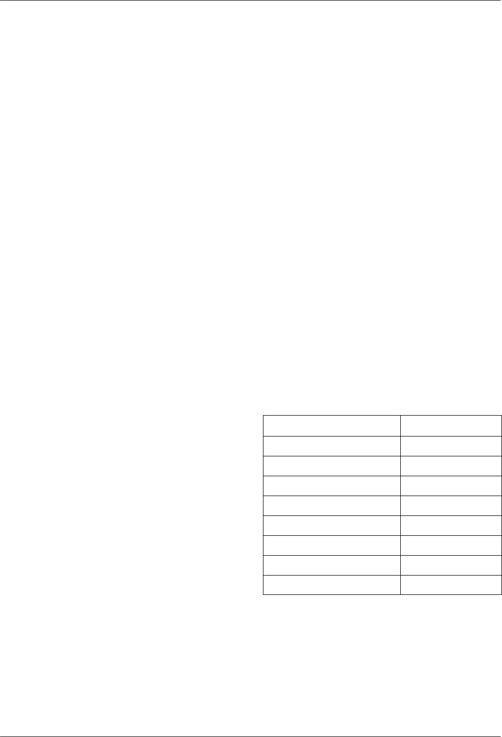
HDSL Network Interface
The HDSL Network interface is an 8-position, unkeyed
modular connector (Table D-1).
Table D-1
HDSL Network Connector
Signal
Pin Number
Loop 2 Ring 1
Loop 2 Tip 2
Unused 3
Loop 1 Ring 4
Loop 1 Tip 5
Unused 6
Unused 7
Unused 8
D