


ACCULINK 336x E1 NTU
C-8 December 1996 3360-A2-GB20-20
Channel Configuration
Options
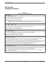
The Channel configuration options are divided into two
tables as follows:
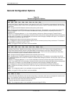
• DTE Channel Configuration Options (Table C-4)
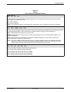
• Data Port Channel Configuration Options
(Table C-5)
NOTE
Tables C-4 and C-5 describe the
DTE and data port configuration
options. For information about the
operation of Display and Clear,
refer to the
Configuring DS0
Channels
section in Chapter 3,
Operation
.
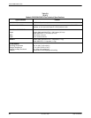
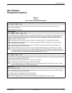
Table C-4
DTE Channel Configuration Options
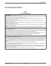
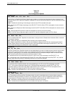
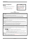
DTE Channels:
TS16 Assign
G.703 DTE Channel. Allows the selection of time-slot 16 (TS16) for signaling information or assigns DS0 channels from
the G.703 DTE interface to DS0 channels on the network interface.
TS16 – Allows the selection of TS16 for signaling information (see the TS16 configuration option below).
Assign – Allows the assignment of DS0 channels from the G.703 DTE interface to the network interface.
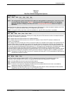
TS16: Data
Data Rsvd CAS
G.703 DTE TS16 Allocation. Specifies whether time-slot 16 (TS16) is reserved for signaling information or available for
data.
Data – Specifies that TS16 is available for data.
Rsvd – Specifies that TS16 is reserved for Common-Channel Signaling information. The time slots must be directly
connected so that the G.703 DS0 channels are connected to the corresponding network DS0 channels (e.g., D1 to N1,
D2 to N2, etc.).
CAS – Specifies that TS16 is reserved for Channel-Associated Signaling information. Except for time-slot 16, the other
time slots do not need to be directly connected as they are in Common-Channel Signaling.
NOTE: Changing this configuration option from one selection to the other (Data, Rsvd, or CAS), deallocates all DS0
channels assigned to either the network interface or the G.703 DTE interface.
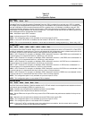
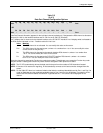
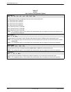
N1 N2 N3 N4 N5 N6 N7 N8 N9 N10 N11 N12 N13 N14 N15 ... N31
– – – – – – – – – – – – – – – ... –
G.703 DTE Channel Allocation. Assigns DS0 channels from the G.703 DTE interface to the network interface.
Line 1 displays the 31 channels for the network interface. Line 2 displays what is allocated to the DS0 channel indicated
in Line 1. Possible values for Line 2 are:
Value
Meaning
– This DS0 channel is not allocated. You can modify this value on this screen.
Prt
n
This DS0 channel is allocated to port
n,
where
n
is a number from 1 to 4. You cannot modify this value
on this screen.
D
n
This DS0 channel is allocated to the G.703 DTE interface DS0 channel
n
, where
n
is a number
from 1 to 31. You can modify this value on this screen.
Assign DTE channels to network channels by pressing the Function key below the network channel desired. The DTE
channel number scrolls up one number each time you press the Function key. Only unassigned DTE channels appear
during scrolling.
NOTE: If time-slot 16 is reserved for signaling (see the TS16 configuration option), D16 is automatically allocated to N16
and will not be available for allocation on this screen.