Installation
2-53360-A2-GB20-20 December 1996
Important Instructions
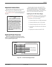
Read and follow all warning notices and instructions
marked on the E1 NTU or included in this guide.
For a complete listing of the safety instructions, see the
Important Safety Instructions section at the beginning of
this guide.
HANDLING PRECAUTIONS
FOR
STATIC-SENSITIVE DEVICES
This product is designed to protect
sensitive components from damage
due to electrostatic discharge (ESD)
during normal operation. When
performing installation procedures,
however, take proper static control
precautions to prevent damage to
equipment. If you are not sure of the
proper static control precautions,
contact your nearest sales or service
representative.
Optional Power Sources
The E1 NTU is typically powered by the ac power
module. Use the following procedures only if you want
to use an optional dc power source.
Using the optional dc power cable, the E1 NTU is
capable of operating on either a +24 Vdc power source,
–48 Vdc single source battery, or –48 Vdc redundant
source batteries (for power backup). To select the power,
choose one of the following power supply types.
Installing the +24 Vdc Power Supply
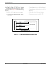
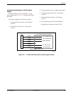
To install the E1 NTU using a +24 Vdc power supply,
refer to Figure 2-9 and use the following procedure.
To install the +24 Vdc power supply,
1. Connect the green wire to a suitable earth ground.
2. Connect the white wire to the +24 Vdc return.
3. Connect the orange wire to the +24 Vdc source.
4. Cut the black, red and blue wires off at the outer
insulation.
5. Plug the power connector into the E1 NTU.
1
2
3
4
5
6
BLACK
RED
GREEN
WHITE
ORANGE
BLUE
EARTH GROUND
+24 VDC RETURN
+24 VDC SOURCE
495-1474
3
X
X
X
NTU POWER
PLUG
TO CUSTOMER-SUPPLIED BATTERY
CABLE NUMBER 3100-F1-520
Figure 2-9. +24 Vdc Power Supply Pinouts


