


ACCULINK 336x E1 NTU
E-2 December 1996 3360-A2-GB20-20
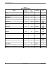
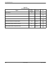
IP Group Supported.
ICMP Group Supported.
TCP Group Not supported since the TCP
protocol is not supported by the
E1 NTU.
UDP Group Supported.
EGP Group Not supported since the EGP
protocol is not supported by the
E1 NTU.
Transmission
Group
Supported on the E1 interfaces
using the DS1/E1 MIB. Supported
on the synchronous data ports
using the RS-232-like MIB.
Supported on the COM and AUX
ports using the RS-232-like MIB.
SNMP Group Supported.
System Group, MIB II
The System Group objects are fully supported by the
E1 NTU. The following sections provide clarification for
objects contained in the System Group where it is not
otherwise clear how the object definition in MIB II is
related to the E1 NTU. Objects not mentioned are
supported as stated in the MIB.
System Group – “sysDescr” Object (system 1)
This object provides the full name and version
identification for the system hardware and software. This
object displays the following string for 2-port and 4-port
E1 NTUs (1-port E1 NTUs do not have H/W CCA2):
E1 HDSL NTU; model: xxxx-xx-xxx; S/W Release:
yy.yy.yy; H/W CCA1: zzzz-zzz; H/W CCA2: zzzz-zzz;
H/W CCA3: zzzz-zzz; Serial number: sssssss.
Where: xxxx-xx-xxx represents the full model
number of the unit.
yy.yy.yy represents the software revision
number of the unit.
zzzz-zzz represents the hardware
revision numbers of the unit.
sssssss represents the serial number of
the unit.
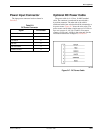
System Group – “sysObjectID” Object
(system 2)
This object provides the authoritative identification of
the network management subsystem contained in the unit.
This object displays the following object identifier:
3360 1.3.6.1.4.1.74.1.14.2.3.2
3364 1.3.6.1.4.1.74.1.14.2.3.3
3365 1.3.6.1.4.1.74.1.14.2.3.4
System Group – “sysServices” Object
(system 7)
This object provides a value which indicates the set of
services that are potentially offered by the E1 NTU. Only
the following values are supported by the E1 NTU.
• physical(1) – Layer 1 functionality for all
interfaces.
• datalink/subnetwork(2) – Layer 2 functionality
(SLIP, PPP) for the COM and AUX ports.
• internet(4) – Layer 3 functionality (IP) for all
management links.
• end-to-end(8) – Layer 4 functionality (UDP) for all
management links.
Therefore, set this object to 15 (the sum
of 1 + 2 + 4 + 8).
Interface Group, MIB II
The Interface Group consists of an object indicating the
number of interfaces supported by the unit and an
interface table containing an entry for each interface. The
E1 NTU provides an entry in the interface table for the
network interface, the G.703 DTE interface, each of the
synchronous data ports (1, 2, or 4 depending on the
model), the COM port, and the AUX port, if they apply.
The following sections provide clarification for objects
contained in the Interface Group where it is not clear how
the object definition in MIB II is related to the E1 NTU.
Interface Group – “ifNumber” Object
(interfaces 1)
This variable contains the maximum number of MIB II
supported interfaces possible across the 33xx Series
product line (9). This is different from the MIB
description, which is defined as the number of interfaces
on the particular device. This change allows the use of the
same ifIndexes across all 33xx Series models.