


ACCULINK 336x E1 NTU
D-4 December 1996 3360-A2-GB20-20
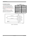
COM Port Interface
The COM port connects to a PC for front panel
emulation, to an ASCII terminal or printer for alarms, to a
network device (e.g., a router) for SNMP applications, to
the SNMP LAN Adapter for SNMP applications, or to
another E1 NTU’s AUX port for daisy chain connectivity.
(The SNMP LAN Adapter includes the cable that is
needed to attach it to the E1 NTU.) The COM port
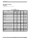
connector is an 8-position keyed modular connector
(Table D-4). The data signals on this port are referenced to
a DTE interface.
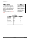
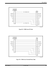
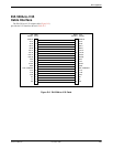
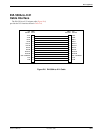
The COM port-to-PC cable is shown in Figure D-2 and
the COM port-to-terminal/printer cable is shown in
Figure D-3.
NOTE
For daisy-chaining an AUX port
to a COM port, a customer
supplied, 8-pin-to-8-pin, straight-
through cable is required and
the appropriate configuration
options (Com Use and Aux Use)
must be set to Daisy. Whenever
the cable is connected or
disconnected, you should
change the Daisy selection to
ensure that the correct
parameters have been
negotiated for the link layer.
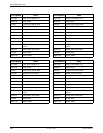
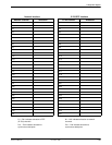
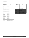
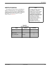
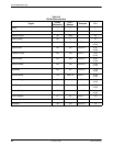
Table D-4
COM Port Connector
Signal
Direction Pin Number
DCE Transmit Clock From NTU 1
DCE Receive Data From NTU 2
Signal Ground — 3
DCE Transmit Data To NTU 4
DCE Data Terminal Ready To NTU 5
DCE Carrier Detect From NTU 6
DCE Request-to-Send To NTU 7
DCE Receive Clock From NTU 8