


ACCULINK 336x E1 NTU
D-2 December 1996 3360-A2-GB20-20
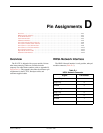
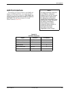
G.703 DTE Interface
The G.703 DTE interface is either two BNC
connectors (Transmit and Receive) for a 75 ohm
unbalanced interface, or a DB15-type socket connector
(Table D-2) for a 120 ohm balanced interface. For
information about using Relay Contact Sense for external
DTE loopback, refer to the Extrn DLB configuration
option in the DTE Interface Configuration Options section
of Appendix C.
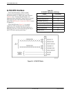
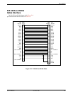
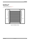
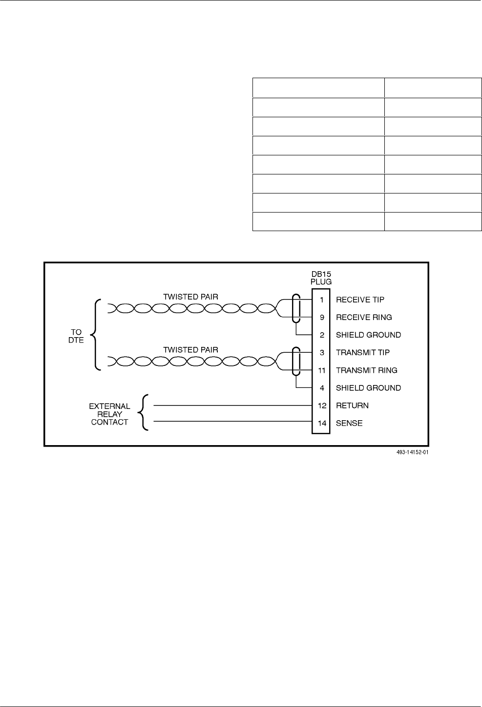
The G.703 DTE cable (Figure D-1) is typically
supplied by a DTE vendor. It is made of shielded
twisted-pair wires (22 AWG). The cable connector is a
DB15 plug. Be sure to connect the shield ground only at
the E1 NTU end to prevent ground loops.
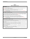
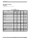
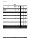
Table D-2
G.703 DTE Connector (120 Ohm)
Signal
Pin Number
Receiver Tip from DTE 1
Receiver Ring from DTE 9
Transmitter Tip to DTE 3
Transmitter Ring to DTE 11
Relay Contact Sense Return 12
Relay Contact Sense 14
Shield Ground 2, 4
Figure D-1. G.703 DTE Cable