


ACCULINK 336x E1 NTU
3-20 December 1996 3360-A2-GB20-20
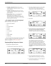
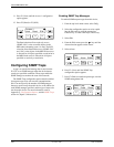
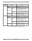
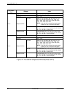
9. Press F1 (Next) until the Trapn Destination
configuration appears, and select the destination
for the SNMP trap by using the appropriate
Function key. Use the scroll keys, if necessary.
F1
Trap
n
Dst:
Next None Com
F2
F3
Configuring DS0 Channels
The E1 NTU provides channel configuration options
that allow you to do the following:
• Display the DS0 assignments for the network,
G.703 DTE, and data port interfaces.
• Allocate DS0 channels on the G.703 DTE interface
to the network interface.
• Allocate DS0 channels on the network or G.703
DTE interface to particular data ports.
• Specify whether time-slot 16 (TS16) is available for
data or reserved for signaling information using
Common-Channel Signaling (CSS) or
Channel-Associated Signaling (CAS).
NOTE
CCS is typically used in a 2-frame
multiframe system, whereas CAS
is used in a 16-frame system.
• Clear (deallocate) all DS0 channels from the
network, G.703 DTE, or data port interface.
• Map data from one port to another.
NOTE
If TS16 is reserved for CCS, D16
will automatically be assigned to
N16, and the G.703 DTE DS0
channels allocated to the network
must be directly connected to the
corresponding channel (e.g., D1
to N1, D2 to N2, etc.).
To allocate DS0 channels, begin by defining the logical
channel configuration for the network interface, and then
the G.703 DTE interface, and then any ports, if desired.
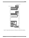
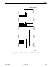
See Figures 3-6 and 3-8 for examples of conceptual
diagrams of channel configurations.
NOTE
With the exception of time-slot 16,
a CAS allocation example is the
same as the example in Figures
3-8 and 3-9. TS16, however, is
directly connected when using
CAS (D16 to N16).
Blank configuration worksheets are provided at the
back of Appendix C, Configuration Options. To complete
the configuration worksheets for DS0 channel allocation:
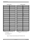
1. Complete the Network Interface and the G.703
DTE Interface tables (unless the G.703 DTE
interface is disabled) as shown in the examples in
Figures 3-7 and 3-9.
2. Using the worksheets shown in Figures 3-10
and 3-11, circle the configuration options needed
to implement the logical channel configuration.
Once you have completed the worksheets, enter this
information using the procedures in the Allocating Data
Ports section on page 3-28. Configuration options are
listed in Appendix C.