SMSC LAN91C111 32/16/8-Bit Three-In-One Fast Ethernet Controller
Revision 1.0 (08-14-08) 16 SMSC AN 9.6
APPLICATION NOTE
READ
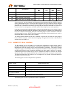
When set (1) the operation is a read; when cleared (0) the operation is a write.
NOT EMPTY
This read-only bit indicates whether the Write Data FIFO is empty or not. The FIFO is not empty when
this bit is set.
POINTER HIGH
These bits comprise the upper three bits of the address.
POINTER LOW
These bits comprise the lower 8-bits of the address. Remember that all access is 32-bits in nature and
therefore the lower two bits are ignored thus allowing all 8K bytes to be accessed.
Reserved
Must be 0.
3.7.3 Data Register
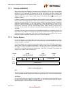
The Data Register comprises the FIFO’s for both transmit and receive side of the Ethernet port. This
FIFO is unidirectional in nature and can normally be read or written in byte, word, or dword aligned
accesses. These accesses can be mixed or matched on the fly. The ability to do byte, word, or dword
access is controlled via the address line A1 and the BE0-BE3 control lines during normal mode of
operation.
If using the nDATACS line to accomplish direct access then all transfers are 32-bits in nature and the
use of A1 and BE0-BE3 is ignored.
The Data Register is mapped into two consecutive word locations for double word operations
regardless of the bus width of the target device (16 or 32 bit). The FIFO depth is 12 bytes each.
For the purpose of this discussion all accesses will be 32-bits in nature because we are using
nDATACS to access the Data Register.
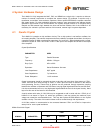
Figure 3.7 Data Register
3.7.4 Timing Analysis Of Direct Access
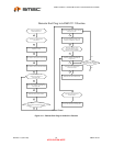
In this section we will examine the timing diagrams using the nDATACS line to control direct access.
3.8 Asynchronous Read or Write Operation – Non Burst
This section will discuss the asynchronous Read or Write operations using the nDATACS signal in a
non-Burst mode.
The timing diagram below details a typical cycle, this could be either a read or write cycle. The use of
the nRD and nWR signals controls the data flow to and from the Data Register. The asynchronous
nature of the nRD or nWR signals along with the absence of an LCLK is why this is referred to as an
asynchronous mode of operation.
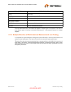
OFFSET
8 THROUGH Bh
NAME
DATA REGISTER
TYPE
READ/WRITE
SYMBOL
DATA
DATA HIGH
X X X X X X X X
DATA LOW
X X X X X X X X


