


SMSC LAN91C111 32/16/8-Bit Three-In-One Fast Ethernet Controller
Revision 1.0 (08-14-08) 8 SMSC AN 9.6
APPLICATION NOTE
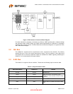
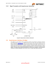
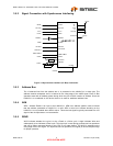
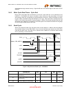
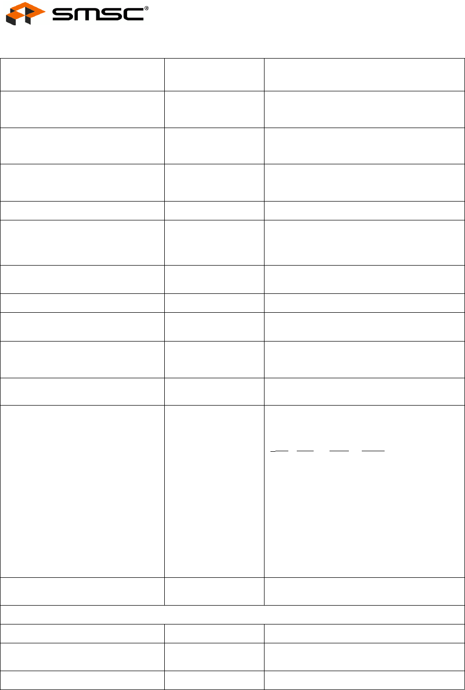
3.5.1 Typical Connection with Synchronous Interface (VL-Bus)
HOST (VL BUS)
SIGNAL
LAN91C111
SIGNAL NOTES
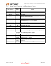
A2-A15 A2-A15 Address bus used for I/O space and register
decoding, latched by nADS rising edgeand
transparent on nADS low time.
M/nIO AEN Qualifies valid I/O decoding - enabled access
when low. This signal is latched by nADS rising
edge and transparent on nADS low time.
W/nR W/nR Direction of access. Sampled by the
LAN91C111 on first rising clock that has
nCYCLE active. High on writes, low on reads.
nRDYRTN nRDYRTN Ready return. Direct connection to VL bus.
nLRDY nSRDY and some
logic
nSRDY has the appropriate functionality and
timing to create the VL nLRDY except that
nLRDY behaves like an open drain output most
of the time.
LCLK LCLK Local Bus Clock. Rising edges used for
synchronous bus interface transactions.
nRESET RESET Connected via inverter to the LAN91C111.
nBE0 nBE1 nBE2 nBE3 nBE0 nBE1 nBE2
nBE3
Byte enables. Latched transparently by nADS
rising edge.
nADS nADS, nCYCLE Address Strobe is connected directly to the VL
bus. nCYCLE is created typically by using
nADS delayed by one LCLK.
IRQn INTR0 Typically uses the interrupt lines on the ISA
edge connector of VL bus
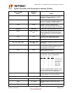
D0-D31 D0-D31
32 bit data bus. The bus byte(s) used to access
the device are a function of nBE0-nBE3:
n
BE0 nBE1 nBE2 nBE3
0 0 0 0 Double word access
0 0 1 1 Low word access
1 1 0 0 High word access
0 1 1 1 Byte 0 access
1 0 1 1 Byte 1 access
1 1 0 1 Byte 2 access
1 1 1 0 Byte 3 access
Not used = tri-state on reads, ignored on writes.
Note that nBE2 and nBE3 override the value of
A1, which is tied low in this application.
nLDEV nLDEV nLDEV is a totem pole output. nLDEV is active
on valid decodes of A15-A4 and AEN=0.
UNUSED PINS
VCC nRD nWR Pull up externally (May through 10KΩ resistor)
GND A1 nVLBUS Pull down externally (May through 10KΩ
resistor)
OPEN nDATACS Leave Open