


SMSC LAN91C111 32/16/8-Bit Three-In-One Fast Ethernet Controller
SMSC AN 9.6 25 Revision 1.0 (08-14-08)
APPLICATION NOTE
these parameters. In this way, many identical boards can be plugged into the same system by simply
changing the IOS strapping.
An additional feature of the LAN91C111 is the ability to change the EEPROM data while in circuit. Even
if the EEPROM was not programmed initially you still have the ability to program the EEPROM via
software. This feature also allows the reprogramming of a previously programmed EEPROM as well.
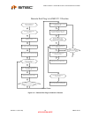
RELOAD and STORE are set by the user to initiate read and write operations respectively. Polling the
value until read low is used to determine completion. When an EEPROM access is in progress the
STORE and RELOAD bits of CTR will read back as both bits high. No other bits of the LAN91C111
can be read or written until the EEPROM operation completes and both bits are clear. This mechanism
is also valid for reset initiated reloads.
One of the IOS combinations is associated with a fixed default value for the key parameters (I/O BASE)
that can always be used regardless of the EEPROM based value being programmed. This value will
be used if all IOS pins are left open or pulled high.
The EEPROM is arranged as a 64 x 16 array. The specific target device is the 9346 1024-bit Serial
EEPROM. All EEPROM accesses are done in words. All EEPROM addresses in the spec are specified
as word addresses.
4.4.1 INDIVIDUAL ADDRESS 20-22 hex
If IOS2-IOS0 = 7, only the INDIVIDUAL ADDRESS is read from the EEPROM. Currently assigned
values are assumed for the other registers. These values are default if the EEPROM read operation
follows hardware reset.
The EEPROM SELECT bit is used to determine the type of EEPROM operation:
a. Normal
b. General Purpose register
a. NORMAL EEPROM OPERATION - EEPROM SELECT bit = 0
On EEPROM read operations (after reset or after setting RELOAD high) the CONFIGURATION
REGISTER and BASE REGISTER are updated with the EEPROM values at locations defined by the
IOS2-0 pins. The INDIVIDUAL ADDRESS registers are updated with the values stored in the
INDIVIDUAL ADDRESS area of the EEPROM.
On EEPROM write operations (after setting the STORE bit) the values of the CONFIGURATION
REGISTER and BASE REGISTER are written in the EEPROM locations defined by the IOS2-IOS0
pins.
The three least significant bits of the CONTROL REGISTER (EEPROM SELECT, RELOAD and
STORE) are used to control the EEPROM. Their values are not stored nor loaded from the EEPROM.
b. GENERAL PURPOSE REGISTER - EEPROM SELECT bit = 1
On EEPROM read operations (after setting RELOAD high) the EEPROM word address defined by the
POINTER REGISTER 6 least significant bits is read into the GENERAL PURPOSE REGISTER.
On EEPROM write operations (after setting the STORE bit) the value of the GENERAL PURPOSE
REGISTER is written at the EEPROM word address defined by the POINTER REGISTER 6 least
significant bits.
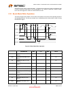
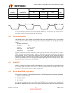
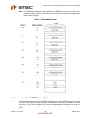
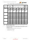
REGISTER EEPROM WORD ADDRESS
Configuration Register
Base Register
IOS Value * 4
(IOS Value * 4) + 1