SMSC LAN91C111 32/16/8-Bit Three-In-One Fast Ethernet Controller
Revision 1.0 (08-14-08) 28 SMSC AN 9.6
APPLICATION NOTE
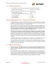
The typical currents measured at the Vcc pins without pullup resistors on the transmit and receive
circuits (Idle condition is defined as state of the chip after powerup (no reset issued), with no link
established):
Approximately 73 mA in the idle state after power up and before reset;
Approximately 100 mA at 100 Mbps, and, approximately 73 mA at 10 Mbps, the typical measured
current was approximately 8 mA in Power down mode, For details of the active supply and powerdown
supply current ranges of the LAN91C111, please refer to the latest datasheet.
4.7 Auto Negotiation
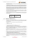
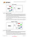
The LAN91C111 integrates the AutoNegotiation Logic to support AutoNegotiation mode. Using this
mode, the chip can automatically configure the device for both 10/100Mbps and Full or Half Duplex. It
also establishes an active link to and from a remote device.
Once the AutoNegotiation mode is initiated, the LAN91C111 will determine if the remote device has
the AutoNegotiation Capability by reading the AutoNegotiation Capable bit of the remote device. (The
AutoNegotiation Capable bit is located in Register 1 bit 3 by the IEEE Standard). If both devices have
AutoNegotiation capability, then both devices uses the contents of the MI Serial Port AutoNegotiation
Advertisement register and Fast Link Pulse's to advertise it capabilities to a remote device.
The capabilities read back from the remote device are stored in the PHY MI Serial port AutoNegotiation
Remote End Capability register. The LAN91C111 negotiation algorithm then matches its capabilities to
the remote device's capabilities and determines what mode the device should be configured to
according to the priority resolution algorithm defined in IEEE 802.3 Clause 28.
Once the AutoNegotiation process is completed, the LAN91C111 then configures itself for either 10 or
100Mbps mode and either Full or Half Duplex modes (depending on the outcome of the negotiation
process), and it switches to either the 100BASETX or 10BASE-T link integrity algorithms.
For more information regarding this procedure or algorithms, refer to IEEE 802.3 Clause 28 for details.
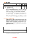
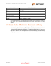
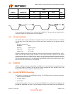
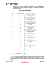
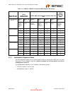
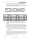
The following tables show the register bit settings for Auto-Negotiation mode and Manual configuration
mode of the LAN91C111:
Table 4.2 LAN91C111 Auto-Negotiation Mode Register Bit Settings
WHAT DO YOU
WANT TO DO?
AUTO-
NEGOTIATION
CONTROL BITS
AUTO-NEGOTIATION ADVERTISEMENT
REGISTER
DUPLEX MODE
CONTROL FOR
THE MAC
Try to Auto-
Negotiate to......
ANEG
Bit
ANEG_EN
Bit
TX_FDX
Bit
TX_HDX
Bit
10_FDX
Bit
10_HDX
Bit
SWFDUP Bit
RPCR
(MAC)
Register 0
(PHY)
Register 4
(PHY)
Register
4 (PHY)
Register
4 (PHY)
Register
4
(PHY)
Transmit Control
Register (MAC)
100 Full Duplex 1 1 1 1 1 1 1
100 Half Duplex 1 1 0 1 1 1 0
10 Full Duplex 1 1 0 0 1 1 1
10 Half Duplex 1 1 0 0 0 1 0


