


SMSC LAN91C111 32/16/8-Bit Three-In-One Fast Ethernet Controller
SMSC AN 9.6 35 Revision 1.0 (08-14-08)
APPLICATION NOTE
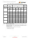
4.11 Thermal Information
For the LAN91C111, 128pin TQFP, the related thermal info can be refer to the below:
Operating Temperature Range 0°C to +70°C for LAN91C111
(The Industrial Temperature Range from -40°C to 85°C for LAN91C111i)
Storage Temperature Range -55°C to + 150°C
Lead Temperature Range (soldering, 10 seconds) +325°C
Junction Temperature Tj = 82°C
Case Temperature Tc = 78°C
Ambient Temperature Ta = 70°C
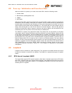
5 Memory Management Unit - Features and Benefits
The SMSC LAN91C111 has an overwhelming advantage over its competition in terms of memory
architecture. The SMSC LAN91C111 has a patented Memory Management Architecture allowing full
dynamic memory allocation for both receive and transmit buffers.
Memory management is handled using a patented, optimized MMU (Memory Management Unit)
architecture and a 32-bit wide internal data path. This I/O mapped architecture can sustain back-to-
back frame transmission and reception for superior data throughput and optimal performance. It also
dynamically allocates buffer memory in an efficient buffer utilization scheme, reducing software tasks
and relieving the host CPU from performing these housekeeping functions.
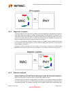
Since the LAN91C111 implements a patented MMU to control allocation and de-allocation of each RX
and TX buffer autonomously, the full extent of the 8Kbytes of shared RX and TX buffers are available
providing a much more flexible memory utilization scheme. As a result, the LAN91C111 solution allows
more memory to be available to the driver and LAN. Also, the LAN91C111’s memory architecture
reduces overrun conditions typical in high latency “real time” operating systems. In embedded
environments, the ability to alleviate overrun conditions improves performance and reduces CPU
overhead.
The patented MMU features the following functions: 1) No Operation, 2) Allocate Memory, 3) Reset
MMU to Initial State, 4) Remove and Release Packets, 5) Enqueue Packets, 6) Reset TX FIFO.
It is recommended that the transmitted and received packets be released immediately after updating
any statistics, to free up buffer memory. If Auto Release feature is used, the MAC automatically
releases the packets after transmission.
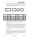
5.1 Memory Partitioning
Unlike other controllers, the LAN91C111 does not require a fixed memory partitioning between transmit
and receive resources. The MMU allocates and de-allocates memory upon different events. An
additional mechanism allows the CPU to prevent the receive process from starving the transmit
memory allocation.
The side that needs it always request memory, for example: the CPU for transmit or the MAC for
receive. The CPU can control the number of bytes it requests for transmit but it cannot determine the
number of bytes the receive process is going to demand. Furthermore, the receive process requests
will be dependent on network traffic, in particular on the arrival of broadcast and multicast packets that
might not be for the node, and that are not subject to upper layer software flow control.