SMSC LAN91C111 32/16/8-Bit Three-In-One Fast Ethernet Controller
SMSC AN 9.6 45 Revision 1.0 (08-14-08)
APPLICATION NOTE
Timing and framing for each management command is to be generated by the CPU (host). For the MII
Serial Frame Structure, please see 7.5.3 of the LAN91C111 datasheet.
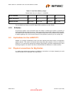
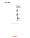
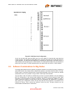
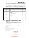
The PHY register set consists of eleven registers. The Control Register and the Status Register are
the Basic Registers defined in the IEEE specification. The basic and fundamental control and status
functions are defined in these two registers. The PHY has six extended registers for providing PHY
Identifier to layer management, providing control and monitoring for Auto-Negotiation Process,
configuration, status output, and Interrupt mask.
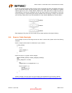
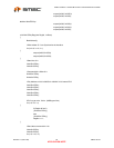
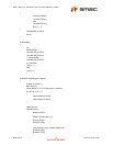
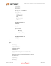
7.3.1 Example Routines To Read and Write the PHY Registers
* Description
* This is to demonstrate the Read and Write procedures for the LAN91C111's
* Internal PHY over the MII.
* To compile this you will need a C/C++ Compiler and LAN91C111 Evaluation
* Evaluation Board.
#include <Stdio.h>
#include <DOS.h>
#define IOP 0x300// LAN91C111 IO Base address
#define BankSelect(x) outport(0x30E,x)
#define WriteZeroToPhy \
outport(0x308, 0x3338);\
outport(0x308, 0x333C);\
outport(0x308, 0x3338);
#define WriteOneToPhy \
outport(0x308, 0x3339);\
REGISTER ADDRESS REGISTER NAME BASIC/EXTENDED
0
Control
B
1
Status
B
2
PHY Identifier
E
3
PHY Identifier
E
4
Auto-Negotiation Advertisement
E
5
Auto-Negotiation Remote End Capability
E
16
Configuration 1
E
17
Configuration 2
E
18
Status Output
E
19
Mask
E
20
Reserved
E


