SMSC LAN91C111 32/16/8-Bit Three-In-One Fast Ethernet Controller
Revision 1.0 (08-14-08) 18 SMSC AN 9.6
APPLICATION NOTE
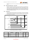
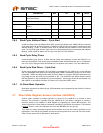
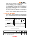
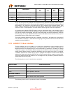
nRDYRTN can be used to insert wait states. In Synchronous mode back to back time between read
or write is limited by access times. From timing diagram, it is 3 clocks for read and 2 clocks for write,
but it has to be bigger than 100ns for read and 80ns for write.
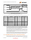
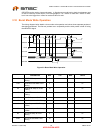
3.10 Burst Mode Write Operation
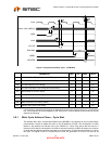
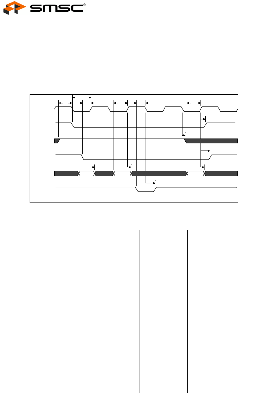
The timing diagram below details a burst mode write operation and shows three separate packets of
data being transferred. The first two packets occur sequentially and the third packet is held off using
the nRDYRTN signal.
Figure 3.9 Burst Mode Write Operation
PARAMETER MIN TYP MAX UNITS
t12 nDATACS Setup to LCLK
Rising
20 ns
t12A nDATACS Hold After LCLK
Rising
0ns
t14 nRDYRTN Setup to LCLK
Falling
10 ns
t15 nRDYRTN Hold after LCLK
Falling
10 ns
t17 W/nR Setup to LCLK Falling 15 ns
t17A W/nR Hold After LCLK Falling 3 ns
t18 Data Setup to LCLK Rising
(Write)
15 ns
t20 Data Hold from LCLK Rising
(White
4ns
t22 nCYCLE Setup to LCLK
Rising
5ns
t22A nCYCLE Hold After LCLK
Rising
10 ns
t15
t20t20t20
t22A
t17A
t12A
t18t14t18
t12
t22t17
ab c
Clock
nDATACS
W/nR
nCYCLE
Write Data
nRDYRTN


