


SMSC LAN91C111 32/16/8-Bit Three-In-One Fast Ethernet Controller
SMSC AN 9.6 9 Revision 1.0 (08-14-08)
APPLICATION NOTE
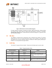
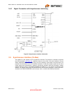
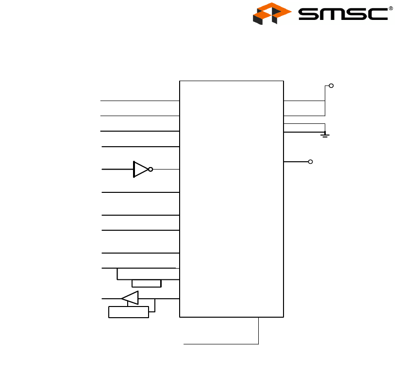
3.5.2 Signal Connection with Synchronous Interfacing
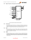
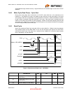
Figure 3.3 Synchronous Interface (VL-Bus) Connection
3.5.3 Address Bus
The 13 address lines form the address bus. It is presented to the LAN91C111 in these pins. The
address remains transparent until it is latched on the rising edge of the nADS signal. Each VL-Bus
operation starts with an address phase during which the pins A15-A2 transfer an address. Since the
LAN91C111 is considered an I/O device, there is no need for additional address lines.
3.5.4 AEN
AEN – Address Enable is an input to the LAN91C111. AEN is an address qualifier used to indicate
that the address presented to LAN91C111 is valid. AEN is active low. Address decoding on the
LAN91C111 is only enabled when AEN is active. This active low signal is typically connected to a nCS
signal of the microprocessor or microcontroller.
3.5.5 W/NR
W/nR indicates whether the cycle is to be a Read or a Write cycle. A high indicates Write and
subsequently a low indicates a Read cycle. This signal pin is used during synchronous bus operations
and can be either connected directly to the CPU or to tri-state buffers. The W/nR is sampled on the
rising edge of the LCLK signal. For asynchronous bus operations, this signal pin should be pulled high
for proper operation.
A2-A15
AEN
INTR0
D0-D31
nBE0-nBE3
nLDEV
LAN91C111
A2-A15
IRQn
D0-D31
nBE0-nBE3
nLDEV
nADS
nADS
delay1
nCYCLE
nSRDY
W/nRW/nR
RESET
+VCC
nR
D
nWR
A1
nVLBUS
nDATACS
(Open)
LCLKLCLK
M/nIO
nRESET
nRDYRTN
O.C.
simulated
O.C.
nLRDY
nRDYRTN