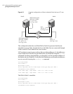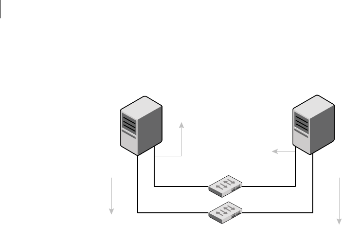
Figure A-1
A typical configuration of direct-attached links that use LLT over
UDP
UDP Endpoint eth1;
UDP Port = 50001;
IP = 192.1.3.1;
Link Tag = link2
UDP Endpoint eth2;
UDP Port = 50000;
IP = 192.1.2.1;
Link Tag = link1
eth1;
192.1.3.2;
Link Tag = link2
eth2;
192.1.2.2;
Link Tag = link1
Switch
Node0 Node1
The configuration that the /etc/llttab file for Node 0 represents has directly
attached crossover links. It might also have the links that are connected through
a hub or switch. These links do not cross routers.
LLT broadcasts requests peer nodes todiscover their addresses. Sothe addresses
of peer nodesdo not need tobe specified in the /etc/llttabfile using the set-addr
command. For direct attached links, you do need to set the broadcast address of
thelinks inthe /etc/llttabfile. Verifythat theIP addressesand broadcastaddresses
are set correctly by using the ifconfig -a command.
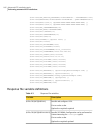
set-node Node0
set-cluster 1
#configure Links
#link tag-name device node-range link-type udp port MTU \
IP-address bcast-address
link link1 udp - udp 50000 - 192.1.2.1 192.1.2.255
link link2 udp - udp 50001 - 192.1.3.1 192.1.3.255
The file for Node 1 resembles:
set-node Node1
set-cluster 1
#configure Links
#link tag-name device node-range link-type udp port MTU \
IP-address bcast-address
Advanced VCS installation topics
Using the UDP layer for LLT
162


