Appendix A: Interfaces
A-26
K1297-G20 Monitor User Manual
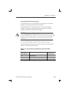
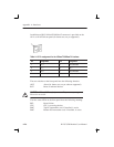
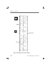
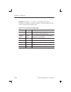
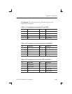
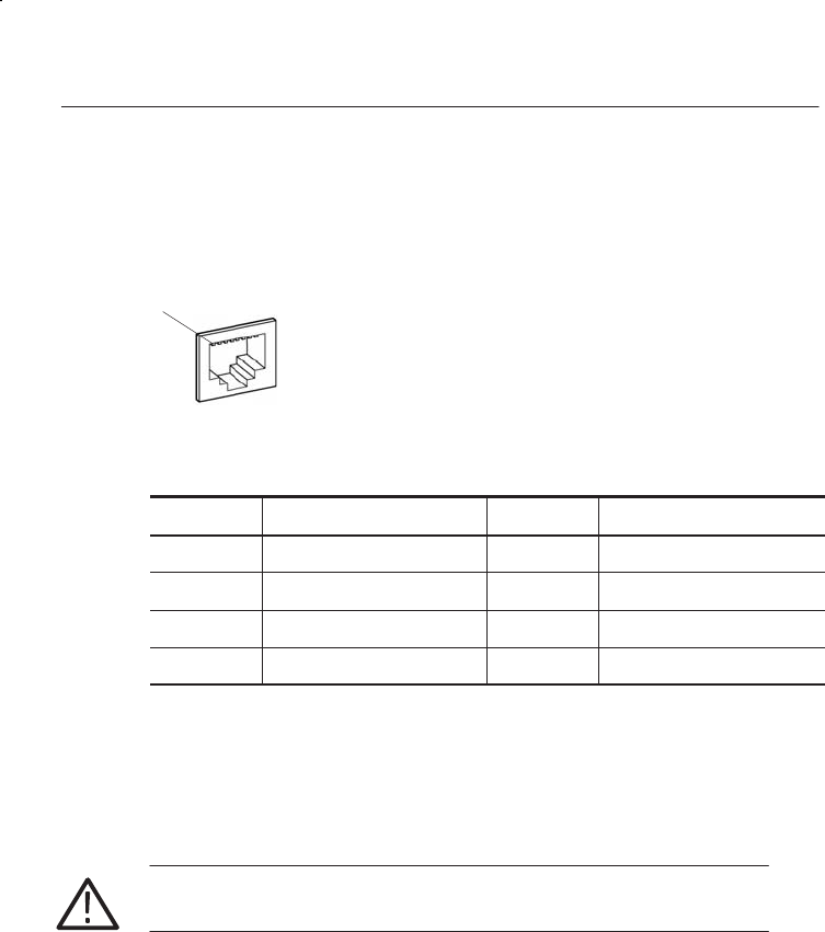
In addition an RJ45 10-BaseT/100-BaseT connector is provided on the
AP-4 or AP-4/256 front panel (for future use, not yet supported).
1
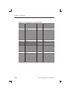
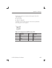
Table A–15: Pin assignment for the 10Base-T/100Base-Tx interface
Pin Assignment Pin Assignment
1 TD + 5 Not connected
2 TD – 6 RD –
3 RD + 7 Not connected
4 Not connected 8 Not connected
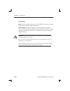
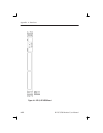
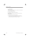
The two switches on the front panel have the following function:
ABT Abort (for future use, not yet software supported)
RST Reset all onboard devices
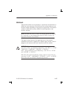
CAUTION. ABT and RST are for future use. They are not yet supported.
Please do not touch.
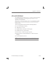
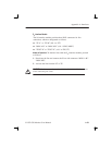
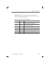
The four status LEDs on the front panel have the following meaning:
BFL Board failure
CPU CPU is accessing the bus
PMC Top PCI mezzanine card, if installed, is active
PMC Bottom PCI mezzanine card, if installed, is active


