


Appendix A: Interfaces
K1297-G20 Monitor User Manual
A-31
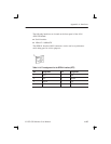
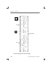
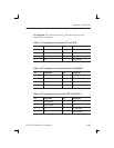
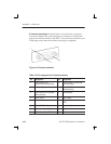
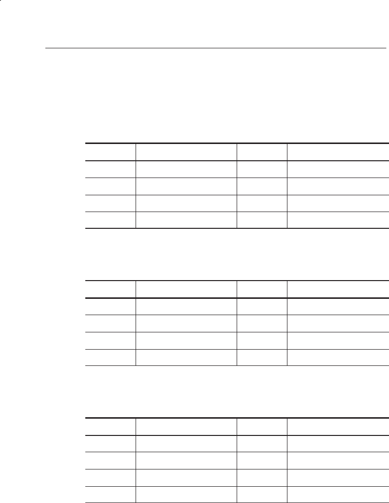
Pin Assignment. The connectors of the S
0
interface module have the
following pin assignment:
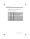
Table A–17: Pin assignment for connectors TE A and TE M
Pin Assignment Pin Assignment
1 Not connected 5 Rx–
2 Not connected 6 Tx–
3 Tx+ 7 Not connected
4 Rx+ 8 Not connected
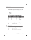
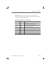
Table A–18: Pin assignment for connectors MON A B and MON M N
Pin Assignment Pin Assignment
1 Not connected 5 Rx TE–
2 Not connected 6 Rx NT–
3 Rx NT+ 7 Not connected
4 Rx TE+ 8 Not connected
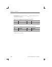
Table A–19: Pin assignment for connectors TE/NT B and TE/NT N
Pin Assignment Pin Assignment
1 Not connected 5 Tx–
2 Not connected 6 Rx–
3 Rx+ 7 Not connected
4 Tx+ 8 Not connected