


Appendix A: Interfaces
A-56
K1297-G20 Monitor User Manual
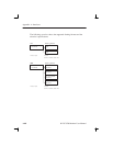
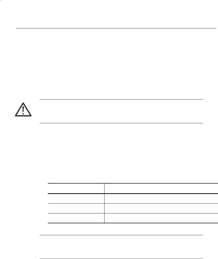
Defining CPU Numbers
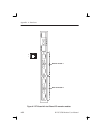
The following section describes how to define CPU numbers (VME bus
addresses) if you work with a second Ethernet board consisting of a
Power-PC board plus hooked up mezzanines. Only an experienced service
technician should perform this setting procedure.
CAUTION. The following steps must be performed at an ESD approved
workplace. Electrostatic discharge can permanently destroy components
that have to be temporarily removed from your device.
In order to operate several Ethernet boards within one device, the default
CPU numbers of the second (third, fourth) board have to be changed.
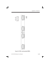
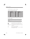
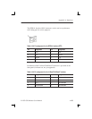
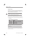
1. Check that the address is set correctly for each board. Typical addresses
are as follows:
Table A–32: Ethernet boards: address settings
Board Address
1st Ethernet board 07 (with 08 implicitly); no changing necessary
2nd Ethernet board 05 (with 06 implicitly)
3rd Ethernet board 03 (with 04 implicitly)
NOTE. Only select odd numbers when changing the address for an
additional Ethernet board, and follow the recommended settings as listed
in the table above.
The CPU numbers being stored within NVRAM of the Ethernet board are
an integral part of the CPU’s bootline. You can modify this bootline as
described in the following.