


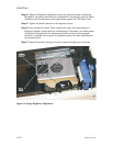
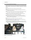
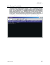
6.4.3 Print Head Peel Bar Position Adjustment
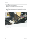
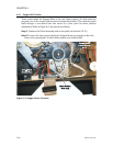
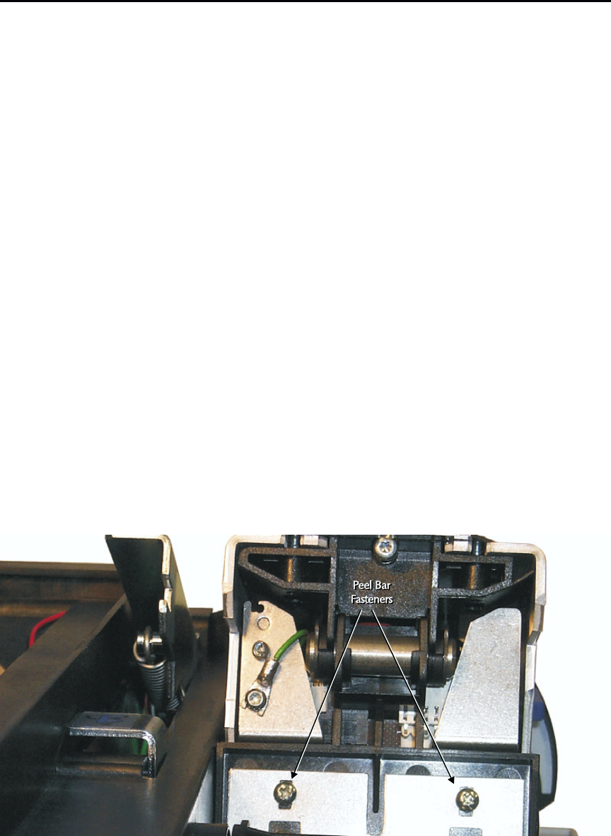
Figure 6-10 shows the two screws that fasten the Peel Bar to the Print Head assembly.
Slotted holes allow Peel Bar positioning. The Peel Bar controls ribbon flow over the Print
Head to establish a centered take up without wrinkling or off-spindle travel. Proceed as
follows:
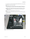
Step 1. Open the Cover, raise the Head, and remove any ribbon.
Step 2. Connect the power and host I/O cables, lower the Cover, Latch down the
Print Heads, and turn power on.
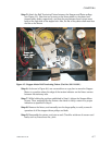
Step 3. Position a 0.02-inch thick card in the card path under the Peel Bar such that
the card resides in Card Guides on both the leading and trailing edges.
Step 4. Latch down the Head, and issue a Head Down command (!D) from the
Window’s print driver or the Test Software (see Appendix A).
Step 5. Sufficiently loosen the two screws securing the Peel Bar to give the bar
freedom of movement. Note that the lower two screws secure other components
and do not interfere with this adjustment.
Step 6. Push down on the Peel Bar until both sides rest on the card.
Step 7. While holding this position, tighten the screws. Afterwards, check for any
displacement from the position established in Step 5.
Step 7. Issue a Head Up command (!M) from the Window’s print driver or the Test
Software, remove the card placed in Step 2, install a ribbon, and print one or more
cards while checking for an even ribbon take up.
6-12 980264-001 Rev.B
CHAPTER 6
Figure 6-10. Peel Bar Fasteners.