


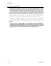
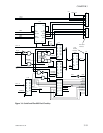
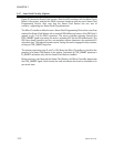
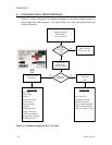

3.4.7 Smart Card Circuitry (Option)
Figure 3-9 shows the Smart Card circuitry. Note that J05 interfaces with the Main Circuit
Board of the printer, and that the DB-9 connector interfaces with the user’s Smart Card
Programming Device. Also note that the Smart Card Station has two sets of
contacts—supporting two Smart Card Chip placements.
The Micro Controller notifies the user’s Smart Card Programming Device that a card has
reached the Smart Card Station with a nominal 220 millisecond return of the DB-9 pin 5
ground to pin 9 of the DB-9 connector. The micro controller activates (lowers) the
CDE_SMART signal to produce this action, actuating K01 for the 220 milliseconds. The
220 nano-farad capacitor and the one-megohm resistor determine the associated K1
activation time. The solenoid remains active, raising the card to engage the chip contacts,
as long as CDE_SMART stays low.
The jumper connecting pins 2 and 3 of J3 allows the Micro Controller to check for the
presence of a Smart Card Station in the printer. Activation of CDE_SMART produces a
D_SMART activation only with the Smart Card Station installed.
Before moving a card beyond the Smart Card Station, the Micro Controller deactivates
the CDE_SMART signal, which lowers the card and allows the circuit to reinitialize to its
pre-active state.
3-22 980264-001 Rev.B
CHAPTER 3