


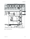
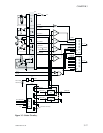
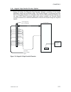
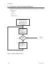

3.4.6 Magnetic Stripe Encoder Circuitry (Option)
Figure 3-8 shows the Magnetic Strip Encoder elements, consisting of the board,
Read/Write heads and associated cables. The Encoder Board is a purchased part that
Eltron Card neither designs nor assembles. Note that the USB and Encoder Boards use
the same CPU Board connector. With both options installed, the Encoder Board
connector attaches to an identical USB Board connector that feeds through the required
signals.
980264-001 Rev. B 3-21
CHAPTER 3
Encoder Board
D16~D31
1
.
.
.
18
19
20
21
22
23
24
25
26
27
28
29
30
31
32
33
34
R_W/
RESET/
GND
GND
CS_MAG
OUTPUT
EXT2
REFERENCE
EENCOD
A1
EXT3
Vdd
Vdd
IRQ4
A0
CS_SUP
J2
CPU Board
Micro Controller
Signals
Read/Write
Heads
USB Configurations
useJ1onUSBBoard
Figure 3-8. Magnetic Stripe Encoder Elements.