


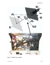

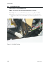
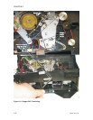
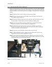

Step 3. Attach the Belt Tensioning Fixture between the Stepper and Platen pulleys
(see Figure 6-5). Note that two cutouts on the fixture attach to the platen and
stepper pulley shafts, respectively, and that the post between these cutouts must
bear on the right side of the stepper belt. Also, the flat of the platen shaft must face
the flat on the fixture.
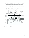
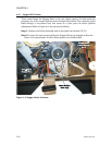
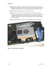
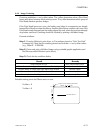
Step 6. As shown in Figure 6-6, use a screwdriver as a pry-bar to move the Stepper
Motor to a position where the edge of the tension indicator on the fixture centers
between the stationary tabs.
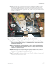
Step 7. While holding the position established in Step 6, tighten the Stepper Motor
Screws. Then, manually flex the fixture a few times to verify a return to a proper
indication as specified in Step 6.
Step 8. Remove the fixture, and manually turn the larger pulley to verify a smooth
operation of all the stepper-driven pulleys and belts.
Step 9. Reassemble the printer, and print a card. Check for evidence of uneven card
feeds, such as, lines across the y axis.
980264-001 Rev. B 6-7
CHAPTER 6
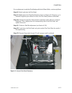
Figure 6-5. Stepper Motor Belt Tensioning Fixture (Part No. 900116-001).