


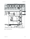
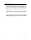
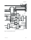
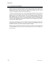

3.4.4 Serial and Parallel Port Circuitry
Figure 3-6 shows the Parallel and Serial Port circuitry. Note that a Serial Host Port is
optional. When used, the Micro Controller supplies the Serial Port data signals. U18 is a
receiver/transmitter that has a built-in charge pump for outputs that require ±10-volt
swings. Note that U18 connects to two port connectors. For these printers, only the host
connection is used.
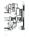
Parallel Port circuits can support bi-directional flow, with 3-state receiver transmitter U37
used to receive or transmit data between J14 and registers U38 and U39. An exchange of
handshake signals controls the flow of data.
The host indicates its desire to send data by activating SELECTIN/* and placing data on
the J14-P0~7 lines. The printer acknowledges by preparing the printer for data reception
and activating ACK/. The Micro Controller raises the R_W/ line and delivers a CS// pulse to
begin the related data read. A BUSY activation results. These, in turn, inform the host that
an activation of STROBE// will transfer the data into the data reception register of the
printer.
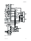
Note that the R_W/ and CS/ signals combine to set the latch (cross-coupled gates) to
activate BUSY and ACK/, and enable U38 (at OC). Also note that activation of STROBE/*
clocks the data into U38 and, with CS/ inactive, resets the latch. Reception or transmission
through U37 is controlled by the Micro Controller via data placed in U40 (signals DIR and
CS 1).
If the printer senses an error, an encoded response is sent to the host over the PERROR
and FAULT/ lines. Possible responses are OK, Command Error, Out of Media, and
Mechanical Error. The Micro Controller loads associated data into U40 during a related
Write Operation.
Write Operations begin with the a CS// pulse with the R_W/ line low. When sending data,
U39 is clocked into U39 by an associated CSWrite/ pulse. Similar to data reception, data
also written into U40 enables U37 and determines its flow direction. Note also that writes
to U40 can activate BUSY and ACK/ if, for example, the Micro Controller needs to hold off
host transfers.
3-18 980264-001 Rev.B
CHAPTER 3