


3.4 CIRCUIT DESCRIPTIONS
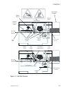
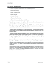
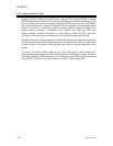
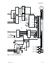
As shown in Figure 3-2, P310 Printers have the following circuits:
•
Print Head Circuiry
•
Motor Control Circuitry
•
Status Circuitry
•
Interface Circuitry
•
Operator Panel Circuitry
•
Optional Encoder and/or Smart Card Circuitry
If possible, spend some time with this figure. The intent is to offer another perspective to
descriptions given in other parts of the manual.
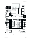
Most of the circuitry resides on the CPU Board. The CPU Board controls the Card Feeder,
Printer Station, reception of Parallel data from the host computer, and to some degree the
optional Smart Card and Magnetic Encoder Stations.
The figure depicts soldered-in circuit blocks without shading. The lighter shading indicates
ICs in sockets. The darker shading indicates external assemblies connected to the CPU
Board by cabling.
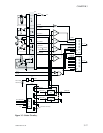
The Micro Controller determines operations through data and address busses and control
signals. Flash memory contains the associated microcode and allows the downloading of
firmware for updates. Note also that the Address Bus primarily serves transfers involving
the Flash and RAM chips.Most other data transfers occur with a chipenable or other Micro
controller signal.
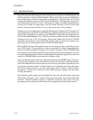
Two types of status are collected—sensor and parameter. Analog Comparators receive
inputs from LED-Photo Transistor sensors. Two types exist—reflective and beam
interrupt. Analog Comparators receive sensor signals on one input and a programmable
voltage on the other. The Micro Controller establishes the comparator thresholds during
calibrations.
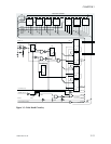
Motors exist intwo types—dc, and stepper. Allassociated driver ICs have socketmounts in
support of IC-level replacement. The Stepper Motor Driver IC has a heat sink. Dc motors
receive 24-volt dc power. This same supply powers a dc-to-dc converter that delivers
5-volt power to the remaining circuitry.
3-10 980264-001 Rev.B
CHAPTER 3