


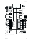
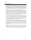
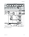
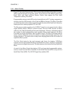

3.4.1 Print Head Circuitry
Figure 3-3 shows the Print Head circuitry. Note that one part lies on the CPU board, and
another part lies on the Print Head Assembly. After a reset, which occurs at initialization,
the processor places 32 bits of image data on the data bus. This data loads into the U12
through U15 registers with activation of the CS HEAD signal. This signal also clears the U9
a and b flip-flops and the U11 counter. At this point, the micro controller has initialized the
circuitry for a transfer of image data to the Print Head. Because of the 672 print head
elements and associated circuitry, 21 such cycles occur prior to any imaging.
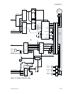
Clocking occurs with deactivation of the CS HEAD signal. Clocking of U12 through U15
shifts image data to the DATA 2 and DATA 4 lines. This sends data to the print head in two
serial streams. Simultaneous clocking at the HEADCLK/ signal shifts the serial data into
the Print Head Shift Registers. U11, which has counted up with each clock, inhibits further
clocking at the count of 32. At this point, all the data loaded with the last CS HEAD
activation has transferred to the Print Head registers, and the circuitry then awaits more
data along with the associated activation of the CS HEAD signal.
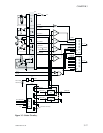
When all 672 print head shift registers have received data, the micro controller activates
the LATCH signal. This transfers the data to associated Print Head Output Registers,
where it becomes available for imaging. At this point, activation of the STROBE signal
causes the print head output registers to activate associated print head elements. For each
line of print head imaging, the micro controller loads the print head registers five times and
issues five STROBE pulses, each time with a different width.
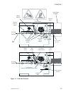
Print head element heat is a function of the pulse width of the STROBE signal. Therefore,
a line for a given ribbon panel color takes five loads of the 672 print head shift registers.
Each Print Head Element receives between zero and five pulse widths, depending on the
dye deposite intensity required. A ribbon advance occurs between the five strobe pulses.
Circuits that deliver power to the print head appear with the Motor Control circuitry
descriptions. Circuits that monitor the print head thermistor appear with the Status
circuitry descriptions.
Monochrome printer imaging occurs similarly but with only one full intensity strobe per
300 dpi line. However, a user could produce gray-scale image using Thermal Transfer
methods. Thermal Transfer employs a small dot matrix for each pixel. The gray
percentage is thena function of the numberof dots imaged within thedot matrix pixels.
3-12 980264-001 Rev.B
CHAPTER 3