


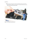
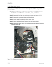
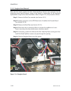
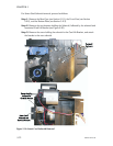

5.2.12 Daughter Board Removal
Note that this board contains the Print Head Up-Down Sensors and connectors for the
remaining sensors and all motors. Access to this board is a prerequisite for all associated
replacements except for the Card Feed Motor. Refer to Figure 5-16, and proceed as follows:
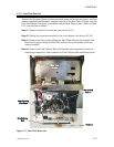
Step 1. Remove the Rear Case member (see Section 5.2.1).
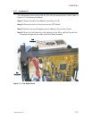
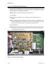
Step 2. Unplug connectors on the CPU Board and, if installed, the Encoder Board
(see Section 5.2.10).
Step 3. Remove the Rear Plate (see Section 5.2.11).
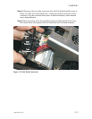
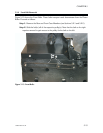
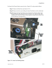
Step 4. Disconnect the six connectors (Note: to prepare for installation of a new
board, note where the three similar motor connectors attach).
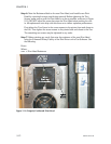
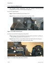
Step 5. If necessary, position the disk used for Print Head Up-Down sensing such that
both Print Head Up/Down sensors can pass through the opening.
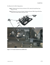
Step 6. Slide the Daughter Board out of the printer.
5-18 980264-001 Rev.B
CHAPTER 5
Figure 5-16. Daughter Board.