


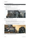
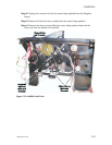


Step 7. Install the new Encoder Head, and replace the overlying parts previously
removed. Feed cables through plastic frame, and to the Encoder Board (see Figure
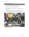
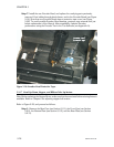
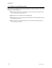
5-14). Note that new Encoder Heads have a protective tape cover (see Figure
5-28). To avoid possible Encoder Head damage, postpone tape removal until just
before replacement of the Shroud. After reassembly, optimize Encoder
performance using the Encoder Test in the Test Software (see Appendix A).
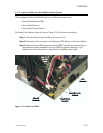
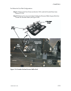
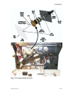
5.2.17 Head Up-Down, Stepper, and Ribbon Take Up Motors
Note: Before replacing theStepper Motor, make sure thatthe associated belt tensioning fixture is
available. Refer to Chapter 6 for adjusting stepper belt tension.
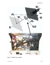
Refer to Figure 5-29, and proceed as follows:
Step 1. Remove the Rear Case (see Section 5.2.1), the Front Case (see Section
5.2.2), the Bottom Plate (see Section 5.2.3), and the Rear Plate (see Section
5.2.11).
5-28 980264-001 Rev.B
CHAPTER 5
Figure 5-28. Encoder Head Protective Tape.