


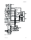
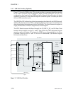
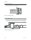
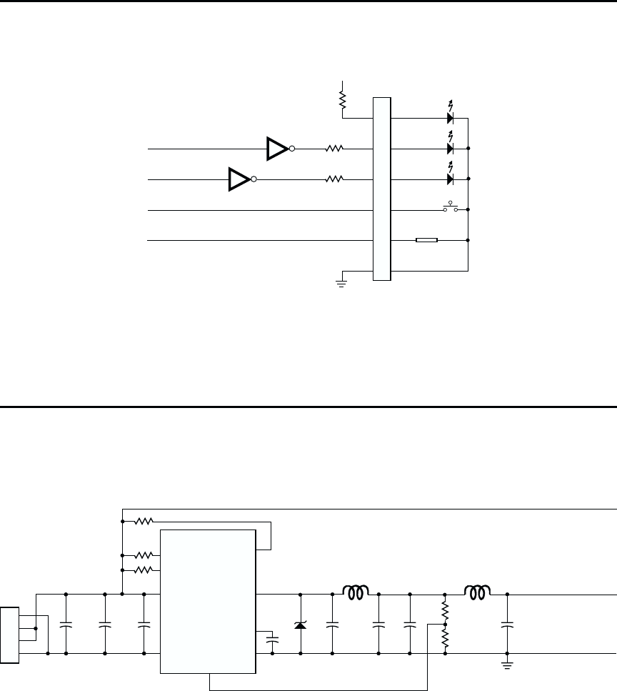
3.4.8 Operator Panel Circuitry
Figure 3-103 shows the circuit elements contained on the Operator Panel Board. The
Micro Controller supplies or receives the signal shown.
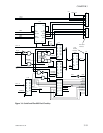
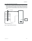
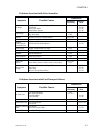
3.4.9 Power Regulator Circuitry
Figure 3-11 shows the power circuitry on the CPU Board. Regulator chip U1 receives
power from the Main Power Supply at J2 and delivers plus 5 volts (Vcc) to the CPU Board.
Note that the Main Power Supply also delivers plus 24 volts to K1 on the CPU Board.
3-24 980264-001 Rev.B
CHAPTER 3
Vcc
J6
330
330
330
D1
D2
D3
BTP1
Contact ILS
L1
L2
IN2
IN3
Figure 3-10. Operator Panel Circuitry
J2
Vin
GND
220pF
6800µF
47µF
SWITCH C
SWITCH E
COMP
CT
DCOL
1 SENSE
GND
270pF
3.3nF
330µH
470µF
33pF
3.6k
1.2k
100nF
Vcc
GND
+24 Volts to K1
4
3
2
1
U1
Figure3-11. Power Regulator Circuitry.