


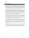
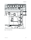
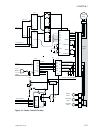
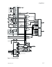
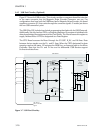
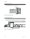
3.4.5 USB Port Circuitry (Optional)
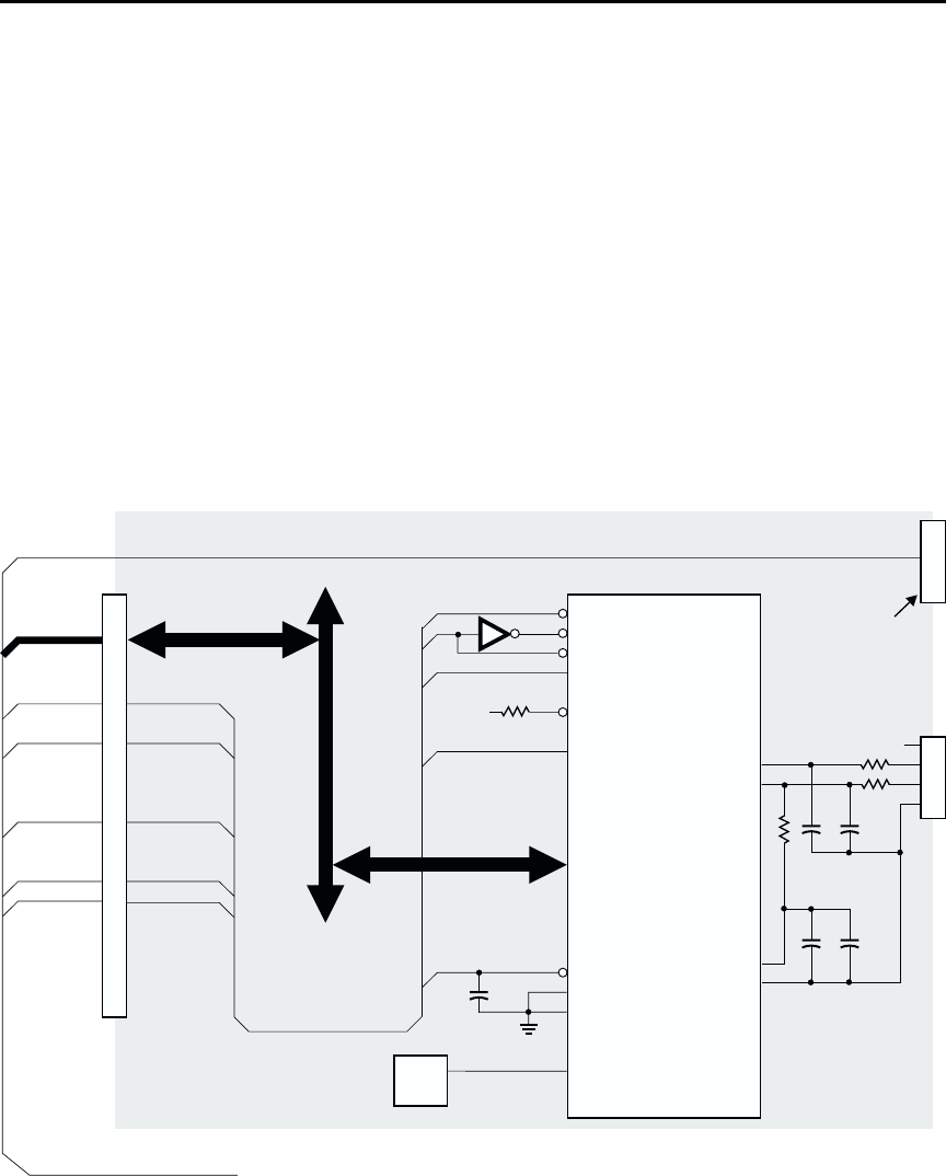
Figure 3-7 shows the USB circuitry. This circuitry resides on a separate board that attaches
to the same connector that the Magnetic Stripe Encoder Connector can use. For
configurations that have both the USB Board and a Magnetic Stripe Encoder, this board
supplies a connector (J1) that carries through the connector signals. J1 resides just above
the non-USB connection point.
The USB Chip (U2) includes hard wired programming that deals with the USB Protocols.
Additionally, the chip has four FIFOs, or Endpoint Registers. One register is initialized with
data characterizing the requirements of the Card Printer. The Host accesses this register to
supply Address Data. A FIFO is designated as a Data Register.
The CPU Board accesses the Board through the CS SUP, R_W/, and A0 lines. Data
between devices travels over the D+ and D- lines. When the FIFO designated for data
reception reaches full status, U2 activates the IRQ4 line, an Interrupt Input to the Micro
Controller. Note that the D+ and D- line are not differential. USB devices support
bi-directional data flows.
3-20 980264-001 Rev.B
CHAPTER 3
/CS
/RD
/WR
INT
DRQ
/DACK
A0
D0
D1
D2
D3
D4
D5
D6
D7
/RST
MODE0
MODE1
CLKOUT
XIN
XOUT
D–
D+
3.3V
AGND
U2
1
2
3
4
J3
Vcc
10k
0.35
0.35
22pF 22pF
1.3k
10nF 10nF
D24~D31
D16~D31
IRQ4
A0
RESET/
CLK
R_W/
CS_SUP
1
.
.
.
18
19
20
21
22
23
24
25
26
27
28
29
30
31
32
33
34
R_W/
RESET/
IRQ4
A0
CS_SUP
GND
GND
CS_MAG
OUTPUT
EXT2
REFERENCE
EENCOD
A1
EXT3
Vdd
Vdd
J2
J1
Magnetic
Stripe
Encoder
Connection
CPU Board
Micro Controller
Si
g
nals
USB BOARD
U3
24MHz
Clock
Figure 3-7. USB Port Circuitry.