


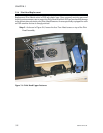
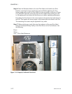
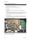
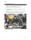

5.2.10 CPU and Encoder Board Replacements
See Appendix A for CPU Board tests. Note that removal of the underlying plate does not
require removal of these boards for the required access. Only unplug the connectors.
Refer to Figure 5-14, and proceed as follows:
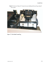
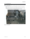
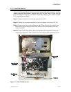
Step 1. Remove the Rear Case member (see Section 5.2.1).
For CPU Board:
Step 2. If desired, replace the circuit component(s) most closely related to the
problem.
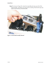
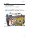
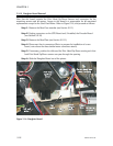
Step 3. If the problem persists, disconnect the board connectors, and remove the four
screws holding the Main Circuit Board. Then, remove the board itself. Note: After
replacing the CPU Board, perform a Printer Setup (see Appendix A).
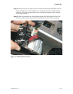
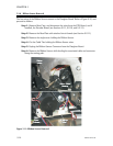
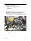
For Encoder Board:
Step 4. Remove the four screws and the CPU Board and Encoder Head Connectors.
Then remove the board. The Encoder Board has no socketed ICs, making board
level replacement the only option.
5-16 980264-001 Rev.B
CHAPTER 5
Figure 5-14. CPU and Encoder Boards.