


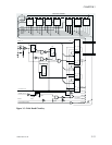
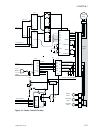
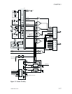
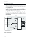

3.4.3 Status Circuitry
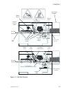
Figure 3-5 shows the Status circuitry. This circuitry allows the Micro Controller to monitor
all the operational status of the basic printer. On the left are Card, Ribbon panel, Flag,
Head Latch, and Head up/Down Sensors. Below these appear the Print Head
Temperature Sensing Thermistor.
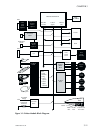
Programmable resistors inside U20 set the threshold levels of U17 analog comparators a
through d and the LED intensity of the Card and Ribbon Sensors. The Micro Controller
can check the states of the analog comparators and the status of the Head Latch Sensor by
loading and then reading registers U31 and U32.
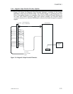
The Flag sensor produces pulses at the R FILM T signal at a rate proportional to ribbon
supply spindle rotation. Without corrective action, the rate would increase as ribbon
collects on the Take Up Spindle and increases its diameter. However, by keeping track of
the number of pulses generated for each complete ribbon panel sequence, the Micro
Controller has a basis for Ribbon Take Up Motor control. The Micro Controller reduces
motor rotation sufficiently to keep the number of pulses approximately equal for each
imaging sequence. The result serves to keep color imaging passes within the confines of
respective ribbon panels.
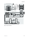
The Print Head raises for fast card transports and lowers for imaging. LED-Photo
transistor sensors signal related Head Up and Head Down status. Cutouts on a disk align
with the sensors to signal these events. Thedisk attaches to the shaft of the Head Up/Down
Motor.
As noted in the Motor Control descriptions, U20, and associated programable resistors,
receive control from the Micro Controller via the Serial Data line (SD1) in step with the
Serial Data Clock (SDK). The CS POT signal chip-enables U20.
3-16 980264-001 Rev.B
CHAPTER 3