


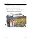
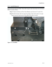
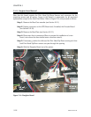
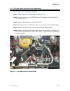
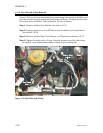
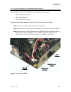
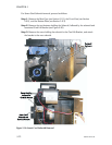
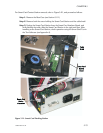
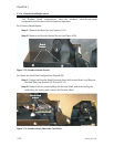
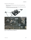
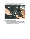

5.2.13 Flag and Head Latch Sensor Board Replacement.
Refer to Figure 5-17, and proceed as follows:
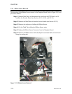
Step 1. Remove the Rear Case Member (see Section 5.2.1).
Step 2. Unplug connectors on the CPU Board and, if installed, the Encoder Board
(see Section 5.2.10).
Step 3. Remove the Rear Plate (see Section 5.2.11).
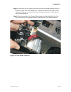
Step 4. Unplug the Flag and Head Latch Sensor connector from the Daughter Board.
Step 5. Raise the Print Head, and unhook the Print Head Release Spring.
Step 6. Remove the single screw holding the Flag and Sensor Board, and remove the
board and associated cable. Note the cable routing in preparation for installation of
the new assembly.
980264-001 Rev. B 5-19
CHAPTER 5
Figure 5-17. Flag and Head Latch Sensor Board.