


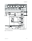
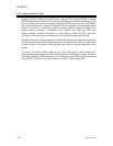
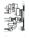
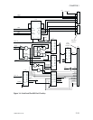

3.4.2 Motor Control Circuitry
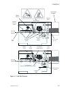
Figure 3-4 shows the Motor Control Circuitry. Stepper Motor inputs PHASE 1 through
PHASE 4 determine the direction of rotation and stepping verses fractional stepping. The
micro controller loads data into registers U26 and U27 through activation of CS MOT.
This data determines the operation of U28. U28 then generates the associated phase
signals. For each of its operations, U28 also requires specific reference voltages. Two
resistor ladder networks in association with outputs from U26 and U27 form
digital-to-analog converters. Therefore, for each loading of U26 and U27, the micro
controller also includes data that determines the reference voltages sent to U28.
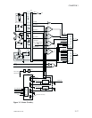
The Micro Controller, through signals sent to U29, determines which dc motor is enabled.
U21 has quad push-pull motor drivers that receive their power from U28. The U28 output
voltage changes as a function of the required motor drive to generate particular motor
speeds.
The Micro Controller enables U28 via the CDE ALIM signal, which activates K1.
Programmable potentiomenters inside U20 determine the U28 output voltage. The Micro
Controller establishes U20 resistances via the U20 Serial Input (SD1) and an associated
clock (SCLK). The Micro Controller activates CS POT to chip-enable U20.
3-14 980264-001 Rev.B
CHAPTER 3