Getting Started
VX1410A & VX1420A IntelliFrame Mainframe Instruction Manual
1–15
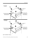
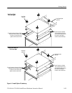
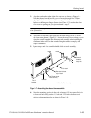
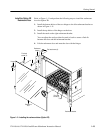
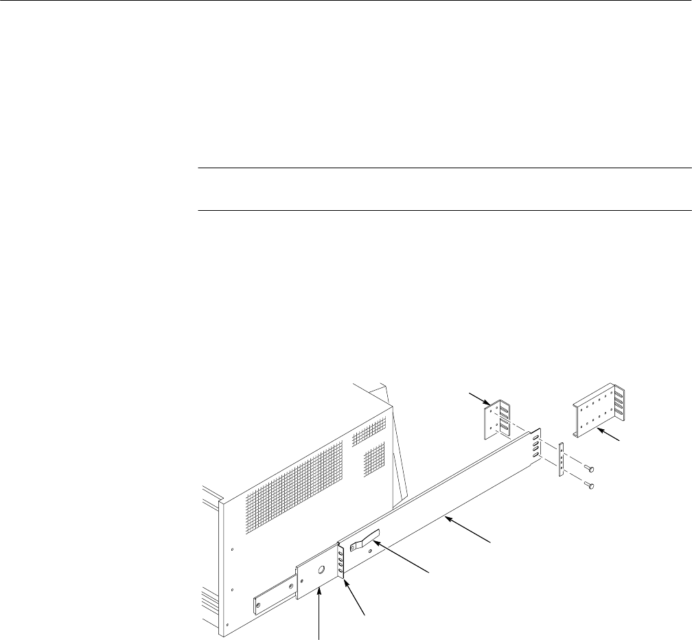
3. Align the rear bracket to the right slide-out track as shown in Figure 1–7.
Note that the rear bracket has two pairs of mount-through holes. When
aligning the bracket and the track, select a pair of holes that mount the rear
bracket so the flange-to-flange distance (see Figure 1–7) matches the front
rail to rear rail spacing that you just measured in step 2.
NOTE. If necessary, refer to the rackmount kit instructions for detailed installa-
tion information.
4. Attach the rear bracket to the right slide-out track using two 10-32 screws
and a bar nut as shown in Figure 1–7. Leave the screws loose so that you can
adjust the overall length of the slide-out track assembly when installing the
mainframe in the rack. Use the extended length brackets to comply with
deeper rackmounts.
5. Repeat steps 3 and 4 to assemble the left slide-out track assembly.
Front of
instrument
Outer track
Inner track
Left Slide-Out Track Assembly
Button latch is closest
to top of track.
Front Flange (mounts
to front rail of rack)
Bracket
Extended
length
bracket for
deep racks
Figure 1–7: Assembling the slide-out track assemblies
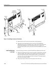
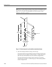
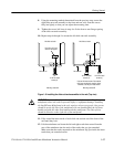
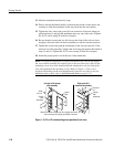
6. Select the mounting position in the rack: select two 0.5-inch spaced holes in
the front rail and verify that the 1.5-inch and 13.25-inch clearances exist
relative to the mounting holes as shown in Figure 1–8.


