


Chapter 4 Tutorials
WiMAX Device Configuration User’s Guide
53
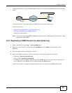
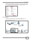
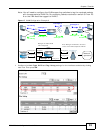
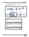
Note: You will need to configure the VLAN supporting switches to tag the received packets
with the appropriate VLAN IDs. For example, packets received on switch S1 from PC
A on the LAN would be tagged to VLAN 5.
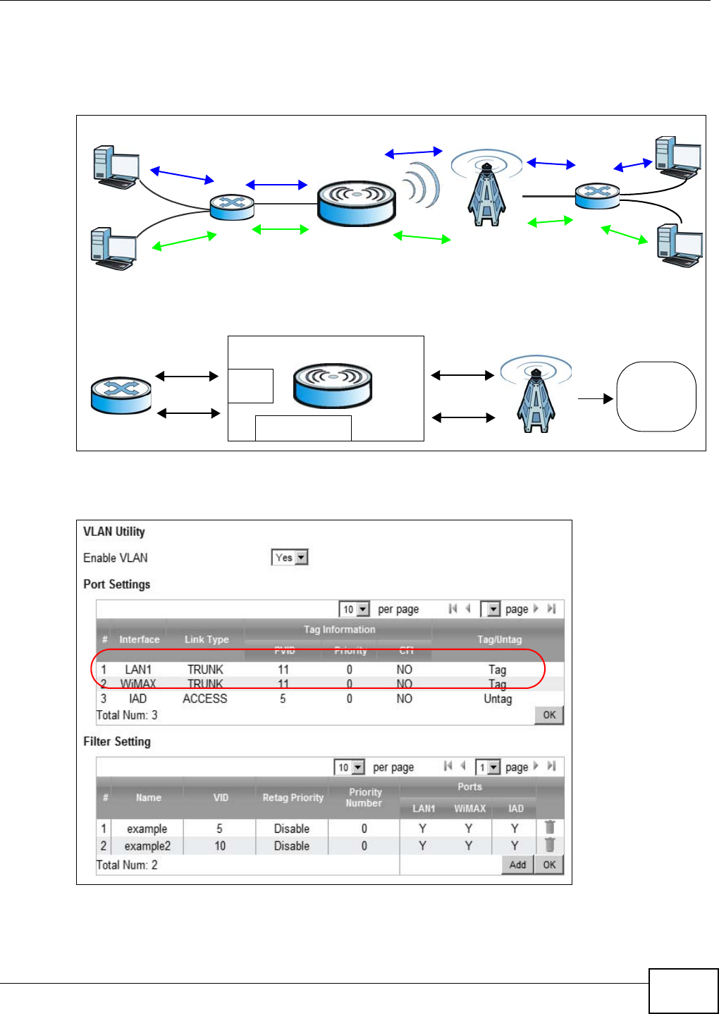
Figure 17 VLAN Configuration Example 2
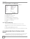
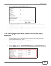
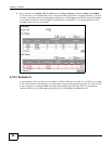
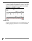
1 Configure the Link Type, PVID and Tag/Untag settings for the interfaces as below by clicking
each row. Then press OK.
VLAN TagID = 5
VLAN TagID = 10
A
B
No VLAN Tag
No VLAN Tag
VLAN TagID = 5
VLAN TagID = 5
VLAN TagID = 10
VLAN TagID = 10
No VLAN Tag
No VLAN Tag
C
D
S1
S2
CPE
LAN
Manager IP
User Network
Router
Manager IP: Enable VLAN
LAN: Transparent
Network
operators
Transparent
Note: Manager IP VLAN ID is the same
as one of the LAN transparent VLAN ID
VLAN Tag ID=5
VLAN Tag ID=5
VLAN Tag ID=10
VLAN Tag ID=10
VLAN Tag ID=5