


3Com Switch 8800 Configuration Guide Chapter 16 IP Routing Protocol Overview
16-3
with the mask 255.255.0.0 is located will be 129.102.0.0. It is made up of several
consecutive "1"s, which can also be expressed in the dotted decimal format.
z Output interface: It indicates an interface through which an IP packet should be
forwarded.
z Next hop address: It indicates the next router that an IP packet will pass through.
z Priority added to the IP routing table for a route: There may be different next hops
to the same destination. These routes may be discovered by different routing
protocols, or they can just be the static routes configured manually. The one with
the highest priority (the smallest numerical value) will be selected as the current
optimal route.
z Path cost: Cost to forward data by the route.
According to different destinations, the routes can be divided into:
z Subnet route: The destination is a subnet.
z Host route: The destination is a host
In addition, according to whether the network of the destination host is directly
connected to the router, there are the following types of routes:
z Direct route: The router is directly connected to the network where the destination
resides.
z Indirect route: The router is not directly connected to the network where the
destination resides.
In order to limit the size of the routing table, an option is available to set a default route.
All the packets that fail to find the suitable entry will be forwarded through this default
route.
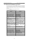
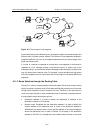
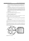
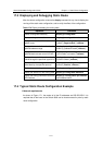
In a complicated Internet as shown in
Figure 16-2, the number in each network is the
network address, and R stands for a router. The router R8 is connected with three
networks, so it has three IP addresses and three physical ports, and its routing table is
shown in the diagram below:
Forwarding Port
router
passed
10.0.0.0
Directly
11.0.0.0
12.0.0.0 11.0.0.2
13.0.0.0 3
14.0.0.0
13.0.0.2
3
15.0.0.0 10.0.0.2 2
16.0.0.0 10.0.0.2
2
15.0.0.0
16.0.0.0
10.0.0.0
13.0.0.0
12.0.0.0
14.0.0.0
11.0.0.0
R4
R1
R3
R2
R6
R5
R7
R
8
1
11.0.0.2
2
12.0.0.1
12.0.0.2
12.0.0.3
14.0.0.1
14.0.0.2
13.0.0.1
13.0.0.4
11.0.0.1
3
10.0.0.1
10.0.0.2
16.0.0.3
16.0.0.2
15.0.0.2
15.0.0.1
13.0.0.2
16.0.0.2
13.0.0.3
The routing table of router R8
Destination
host
location
Directly
Directly
2
1
1
Figure 16-2 The routing table