


3Com Switch 8800 Configuration Guide Chapter 21 BGP Configuration
21-28
Configure Switch C:
[Switch C] bgp 1003
[Switch C-bgp] confederation id 100
[Switch C-bgp] confederation peer-as 1001 1002
[Switch C-bgp] group confed1001 external
[Switch C-bgp] peer confed1001 as-number 1001
[Switch C-bgp] group confed1002 external
[Switch C-bgp] peer confed1002 as-number 1002
[Switch C-bgp] peer 172.68.10.1 group confed1001
[Switch C-bgp] peer 172.68.10.2 group confed1002
[Switch C-bgp] group ebgp200 external
[Switch C-bgp] peer 156.10.1.2 group ebgp200 as-number 200
[Switch C-bgp] group ibgp1003 internal
[Switch C-bgp] peer 172.68.1.2 group ibgp1003
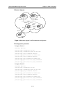
21.4.2 Configuring BGP Route Reflector
I. Network requirements
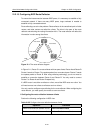
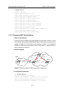
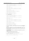
Switch B receives an update packet passing EBGP and transmits it to Switch C. Switch
C is a reflector with two clients: Switch B and Switch D. When Switch C receives a route
update from Switch B, it will transmit such information to Switch D. It is required to
establish an IBGP connection between Switch B and Switch D, because Switch C
reflects information to Switch D.
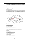
II. Network diagram
IBGP IBGP
EBGP
Client
Client
Route reflector
VLAN 4
194.1.1.1/24
VLAN 3
193.1.1.1/24
VLAN 3
193.1.1.2/24
VLAN 4
194.1.1.2/24
VLAN 2
192.1.1.2/24
VLAN 2
192.1.1.1/24
AS100
AS200
Network
1.0.0.0
VLAN 100
1.1.1.1/8
Switch A
Switch B
Switch C
Switch D
Figure 21-3 Network diagram for BGP route reflector configuration
III. Configuration procedure
1) Configure Switch A:
[Switch A] interface vlan-interface 2
[Switch A-Vlan-interface2] ip address 192.1.1.1 255.255.255.0
[Switch A-Vlan-interface2] interface Vlan-interface 100
[Switch A-Vlan-interface100] ip address 1.1.1.1 255.0.0.0