


3Com Switch 8800 Configuration Guide Chapter 37 BGP/MPLS VPN Configuration
37-69
networks at the city level into a single MPLS VPN will impose a high requirement in
performance on the equipment on the entire network, in the event that the network
topology size is large. However, the requirement in equipment performance can
become lower if this MPLS VPN is separated into two VPNs, the network at the
province level and the network at the city level, for example.
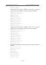
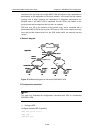
SPE acts as a PE on the network at the province level, and is connected with a
downstream MPLS VPN at the city level. UPE acts as a PE on the network at the city
level and provide access service for the VPN clients which are normally low-end
routers.
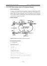
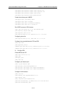
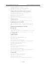
II. Network diagram
MPLS
骨干网
PE
PE
SPE
Upper VPN
Lower VPN
UPE
CE
CE
CE CE
VPN1 Site1 VPN2 Site1
VPN1 Site1
VPN2 Site1
UPE
VLAN201
10.0.0.1/8
VLAN301
10.0.0.2/8
Loopback0:10.0.0.2
Loopback0:1.0.0.1
MPLS backbone
PE
PE
SPE
UPE
CE
CE
CE CE
VPN1 Site1 VPN2 Site1
VPN1 Site1
VPN2 Site1
UPE
VLAN201
10.0.0.1/8
VLAN301
10.0.0.2/8
Loopback0:10.0.0.2
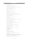
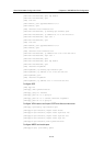
Figure 37-15 Network diagram for hierarchical BGP/MPLS VPN
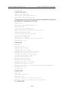
III. Configuration procedure
Note:
This case only illustrates the configurations concerned with PEs in a hierarchical
BGP/MPLS VPN.
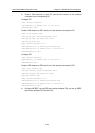
1) Configure SPE
Configure the basic MPLS capability.
[SPE] mpls lsr-id 1.0.0.2
[SPE] mpls
[SPE-mpls] quit