


3Com Switch 8800 Configuration Guide Chapter 41 VRRP Configuration
41-9
41.3 Displaying and debugging VRRP
After the above configuration, execute display command in any view to display the
running of the VRRP configuration, and to verify the configuration. Execute debugging
command in user view to debug VRRP configuration.
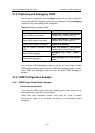
Table 41-10 Display and debug VRRP
Operation Command
Display VRRP state information
display vrrp [ interface vlan-interface
interface-num [ virtual-router-ID ] ]
Display VRRP statistics information
display vrrp statistics [ vlan-interface
interface-num [ virtual-router-ID ]
Display VRRP summary information
display vrrp summary
Clear the statistics information about
VRRP
reset vrrp statistics [ vlan-interface
interface-num [ virtual-router-ID ] ]
Enable VRRP debugging.
debugging vrrp { state | packet |
error }
Disable VRRP debugging.
undo debugging vrrp { state | packet |
error }
You can enable VRRP debugging to check its running. You may choose to enable
VRRP packet debugging (option as packet), VRRP state debugging (option as state),
and/or VRRP error debugging (option as error). By default, VRRP debugging is
disabled.
41.4 VRRP Configuration Example
41.4.1 VRRP Single Virtual Router Example
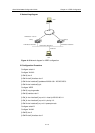
I. Networking requirements
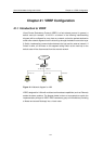
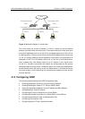
Host A uses the VRRP virtual router which combines switch A and switch B as its
default gateway to access host B on the Internet.
VRRP virtual router information includes: virtual router ID1, virtual IP address
202.38.160.111, switch A as the Master and switch B as the Backup allowed
preemption.